Executive Summary 摘要
Many of the vulnerabilities and attacks Team82 writes about and presents all over the world at conferences may seem somewhat abstract. We talk about critical vulnerabilities in industrial equipment and connected cyber-physical systems, but in reality, it’s difficult to visualize the consequences of, for example, injecting an engineering workstation with code that is downloaded to a programmable logic controller (PLC) that disrupts or shuts down an industrial process.
Team82 在世界各地的会议上撰写和展示的许多漏洞和攻击可能看起来有些抽象。我们谈论工业设备和互联网络物理系统中的关键漏洞,但实际上,很难想象例如,将下载到可编程逻辑控制器 (PLC) 的代码注入工程工作站的后果,从而中断或关闭工业过程。
We decided to throw back the curtain and help you visualize an attack against a factory floor through the use of a virtual environment called Factory/IO. We won’t be disclosing a new vulnerability or attack against operational technology. Instead, we’ll build a virtual factory inside this environment, and demonstrate a general layout and implementation of typical components, such PLCs, sensors, actuators, and an HMI as well to oversee this plant.
我们决定揭开帷幕,通过使用名为 Factory/IO 的虚拟环境,帮助您可视化对工厂车间的攻击。我们不会披露针对运营技术的新漏洞或攻击。取而代之的是,我们将在此环境中构建一个虚拟工厂,并演示典型组件(如 PLC、传感器、执行器和 HMI)的总体布局和实现,以监督该工厂。
Building such a playground can allow us to not only simulate real world representation of a factory, but illustrate the dependencies between these systems, and also provide us a controlled environment to test different threat models and methodologies in an industrial setting.
构建这样一个游乐场不仅可以让我们模拟工厂的真实世界表示,还可以说明这些系统之间的依赖关系,还可以为我们提供一个受控环境,以便在工业环境中测试不同的威胁模型和方法。
In part one, we’ll: 在第一部分中,我们将:
-
Define some basic OT terminology
定义一些基本的 OT 术语 -
Use Factory/IO to build our simulated environment
使用 Factory/IO 构建我们的模拟环境 -
Connect our factory to Rockwell Automation’s Control Logix5000 1765 L71 PLCs
将我们的工厂连接到罗克韦尔自动化的 Control Logix5000 1765 L71 PLC -
Program the PLC using structured text (ST) through Rockwell’s RSLogix5000 software
通过罗克韦尔的 RSLogix5000 软件使用结构化文本 (ST) 对 PLC 进行编程 -
Set up an Inductive Automation Ignition HMI that will allow us to design an HMI panel and visualize industrial processes inside our plant
设置感应式自动化点火 HMI,使我们能够设计 HMI 面板并可视化工厂内的工业流程
In part 2 of this series, we showcase different attack techniques on OT technologies. This information should be especially useful for IT cybersecurity staff who are new to OT. Using this type of modeling and scenario helps visualize where risk may need to be managed and how actual exploits can interrupt or disrupt processes managed by OT equipment and impact the bottom line.
在本系列的第 2 部分中,我们将展示针对 OT 技术的不同攻击技术。此信息对于不熟悉 OT 的 IT 网络安全人员尤其有用。使用这种类型的建模和场景有助于可视化可能需要管理风险的地方,以及实际漏洞如何中断或破坏 OT 设备管理的流程并影响底线。
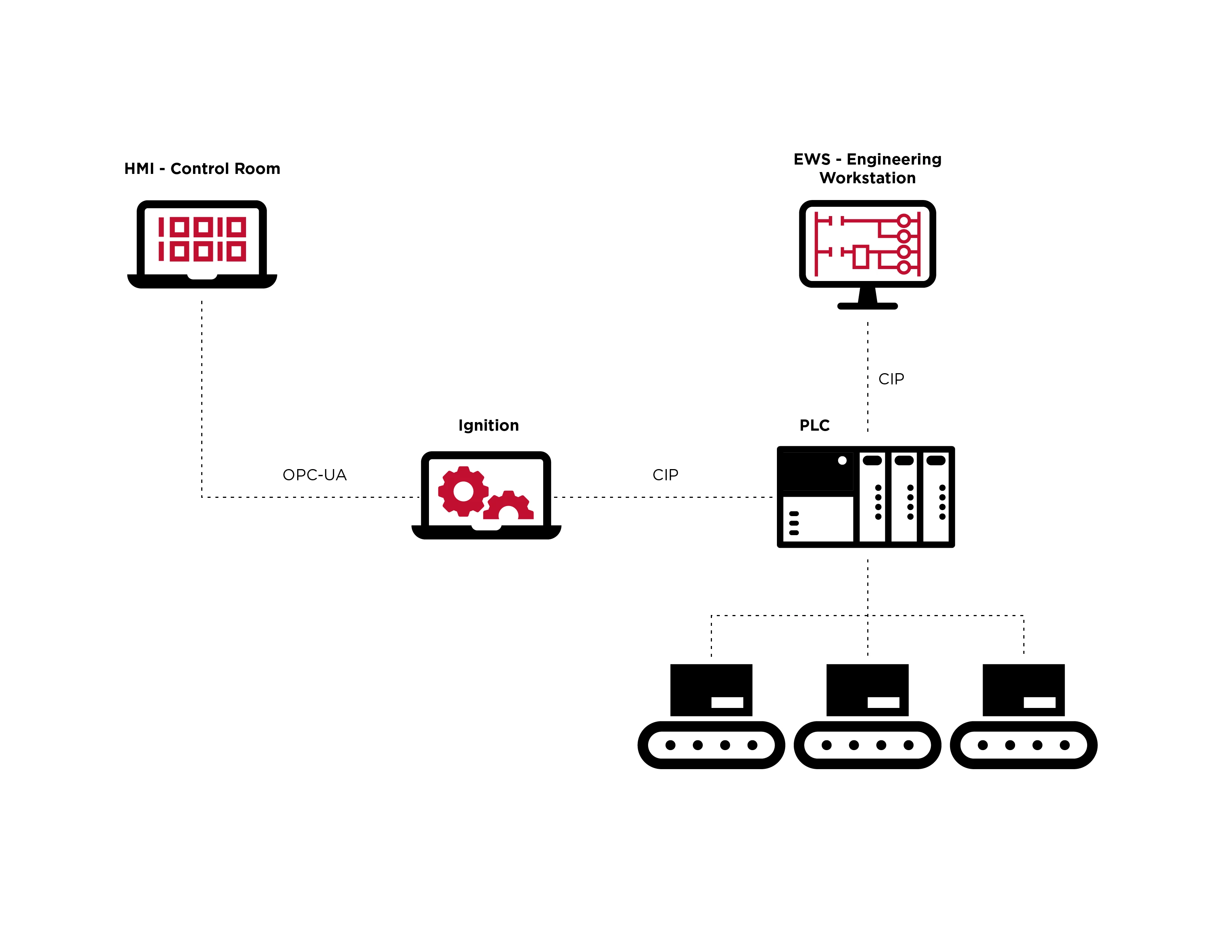
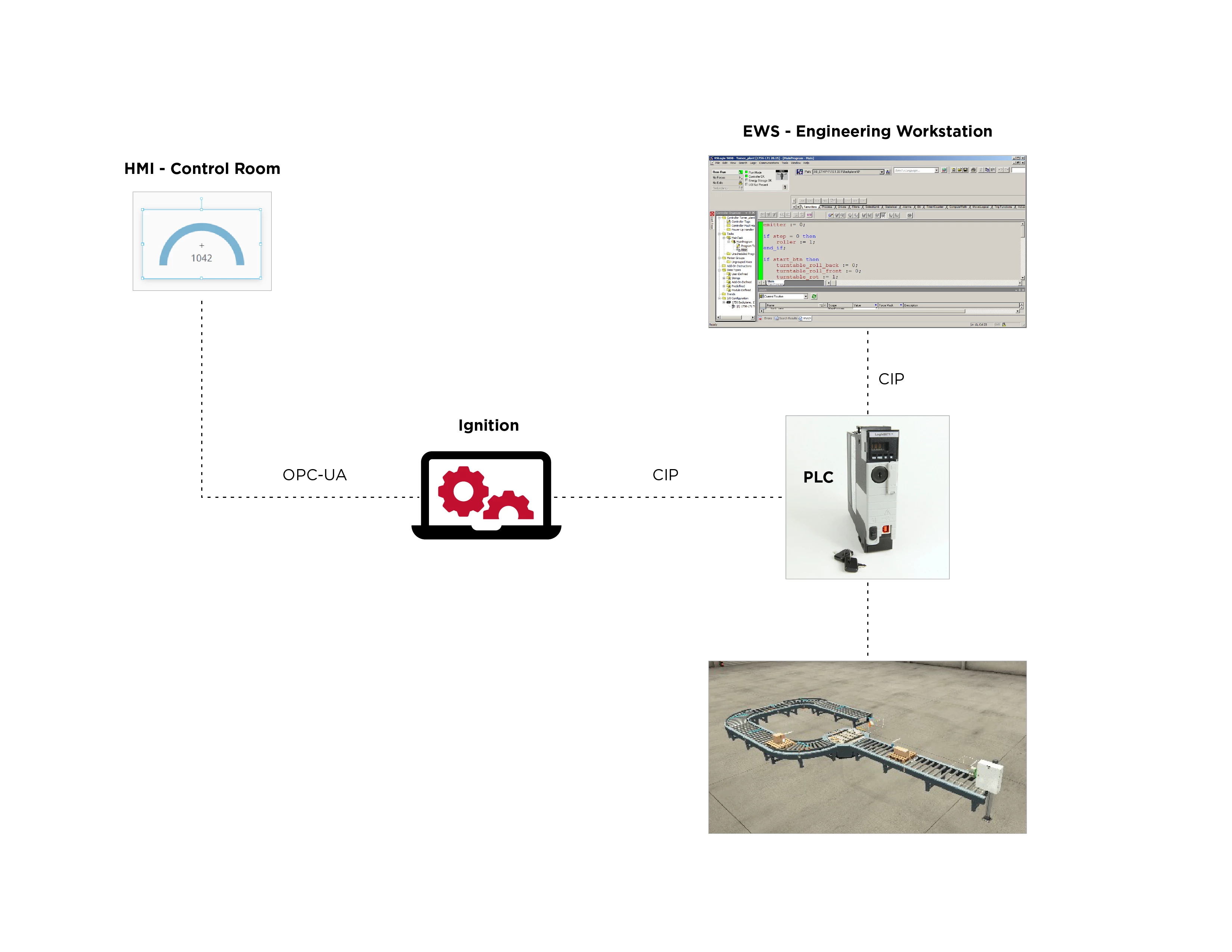
下面是我们将在模拟工厂环境中使用的一些组件的高级表示,它们通信的协议,以及这些组件之间的依赖关系的显示。
Before we begin, let’s define some basic terms:
在开始之前,让我们定义一些基本术语:
-
Programmable Logic Controller (PLC): A rugged computer that processes customized programming for particular industrial tasks.
可编程逻辑控制器 (PLC):一种坚固耐用的计算机,可处理特定工业任务的定制编程。 -
Engineering Workstation (EWS): An application—generally Windows-based—used to program and deploy automation logic to PLCs
工程工作站 (EWS):一种应用程序(通常基于 Windows),用于对自动化逻辑进行编程并将其部署到 PLC -
HMI (Human Machine Interface): A user interface that a person can use to monitor and control industrial processes by visualizing data, tracking production processes, and monitor programming changes to devices
HMI(人机界面):一种用户界面,人们可以使用它来通过可视化数据、跟踪生产过程和监控设备的编程更改来监视和控制工业过程 -
CIP (Common Industrial Protocol): This protocol, developed by Rockwell Automation, is used to organize and represent data on the OT network, as well as manage connections and messaging.
CIP(通用工业协议):该协议由罗克韦尔自动化开发,用于组织和表示 OT 网络上的数据,以及管理连接和消息传递。
Factory Simulation Acts as Threat Modeling Testbed
工厂仿真充当威胁建模测试平台
Factory/IO produces 3D factory simulations, and is generally used as a PLC training platform, the company says in its documentation. Users can build a virtual factory using its drag-and-drop interface with parts commonly found in typical industrial applications.
该公司在其文档中表示,Factory/IO产生3D工厂模拟,通常用作PLC培训平台。用户可以使用其拖放界面构建虚拟工厂,其中包含典型工业应用中常见的零件。
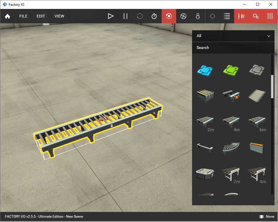
在 Factory/IO 中将传送带拖到我们的工厂中。
Using Factory/IO, we built a simple assembly line segment that transfers pallets with merchandise through our factory. Our assembly line consists of a series of conveyor belts and a turntable that rotates according to sensors that recognize the presence of pallets in their sight. The assembly line is carefully orchestrated by the different states of the sensors. Each sensor is positioned in a way that indicates the position of a pallet on the assembly line.
使用 Factory/IO,我们构建了一个简单的装配线段,通过我们的工厂转移装有商品的托盘。我们的装配线由一系列传送带和一个转盘组成,转盘根据传感器旋转,这些传感器可以识别托盘的存在。装配线由传感器的不同状态精心编排。每个传感器的定位方式都指示托盘在装配线上的位置。
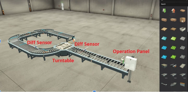
我们在 Factory/IO 中组装的已完成工厂的屏幕截图。
Connecting and Programming our PLC
连接和编程我们的 PLC
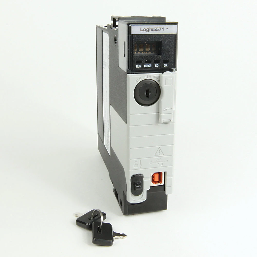
The next stage for our factory assembly is the wiring of the sensors and actuators to the PLC. The PLC we intend to use is the 1756-L71 CPU of the ControlLogix series from Rockwell Automation.
我们工厂组装的下一阶段是将传感器和执行器连接到 PLC。我们打算使用的 PLC 是罗克韦尔自动化 ControlLogix 系列的 1756-L71 CPU。
In order to make our virtual factory as close to reality as possible, we synchronized the virtual PLC inside the Factory/IO software to a physical PLC. To do so we need to go to the File → Drivers screen and configure the EtherNet/CIP driver that will communicate with our physical PLC. Configuring this connection will allow the real PLC to be in charge of our factory machinery by controlling the wired sensors and actuators that we placed inside our simulated factory.
为了使我们的虚拟工厂尽可能接近现实,我们将工厂/IO 软件中的虚拟 PLC 同步到物理 PLC。为此,我们需要转到 File → Drivers 屏幕并配置将与我们的物理 PLC 通信的 EtherNet/CIP 驱动程序。 配置此连接将允许真正的 PLC 通过控制我们放置在模拟工厂内的有线传感器和执行器来负责我们的工厂机器。
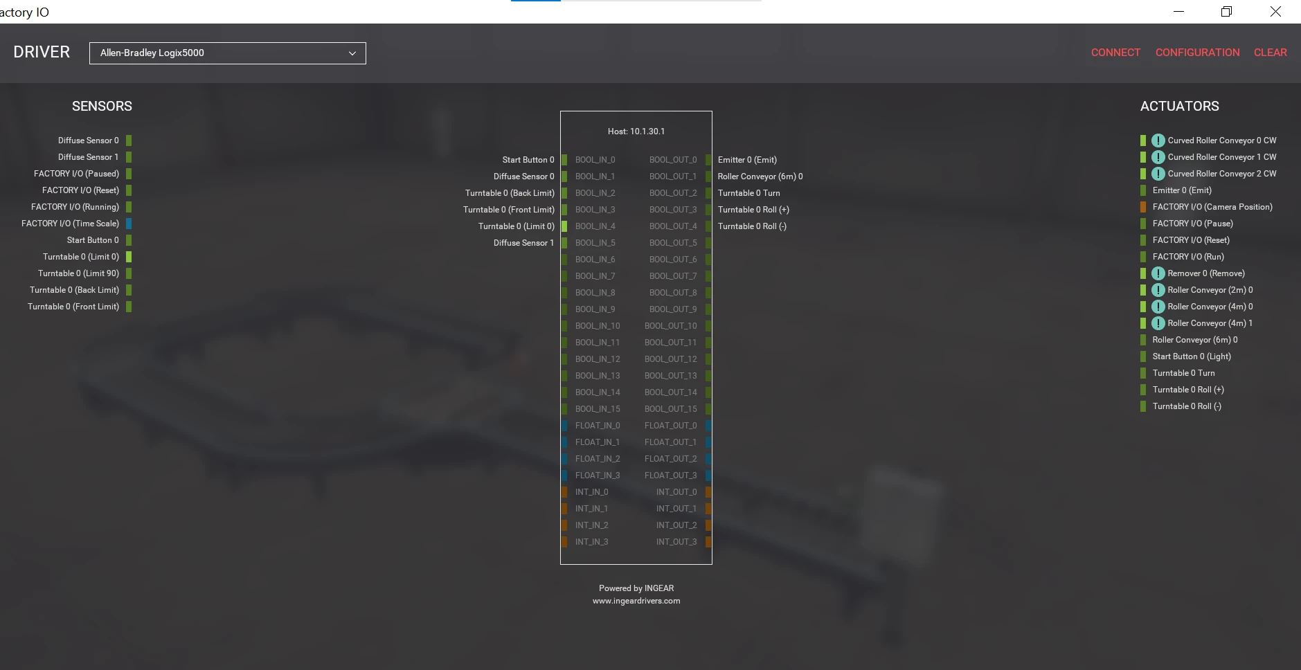
Factory/IO 应用程序中“驱动程序”视图的屏幕截图。在此视图中,我们使用虚拟传感器和执行器配置输入和输出
In order to program the PLC, we use our engineering workstation and open the RSLogix5000 (older version of Studio5000) software package to start building our automation logic using the structured text language.
为了对 PLC 进行编程,我们使用我们的工程工作站并打开 RSLogix5000(旧版本的 Studio5000)软件包,开始使用结构化文本语言构建我们的自动化逻辑。
We start our PLC programming by declaring the tags we are going to use in the automation script. Tags are similar to variables that hold data; they are used in industrial processes to represent a certain value of the underlying process. For example a tag can represent a temperature measurement inside a boiler and will be of the type integer.
我们通过声明要在自动化脚本中使用的标签来开始 PLC 编程。标签类似于保存数据的变量;它们在工业过程中用于表示基础过程的某个值。例如,标签可以表示锅炉内的温度测量值,并且类型为整数。
In our factory, we have several components that are represented by tags inside our PLC program.
在我们的工厂中,我们有几个组件,这些组件在我们的 PLC 程序中由标签表示。
For instance, the on/off state of a diffuse sensor will be represented by a boolean tag of a single bit which holds true/false values and indicates the presence of a physical object in front of the sensor.
例如,漫反射传感器的开/关状态将由单个位的布尔标签表示,该标签保存真/假值,并指示传感器前方存在物理对象。
Inside the RSLogix5000 software, we define the different components represented by IO artifacts inside the program. We can also create aliases to have more meaningful names to use inside our structured text program.
在 RSLogix5000 软件中,我们定义了程序内由 IO 工件表示的不同组件。我们还可以创建别名,以便在我们的结构化文本程序中使用更有意义的名称。
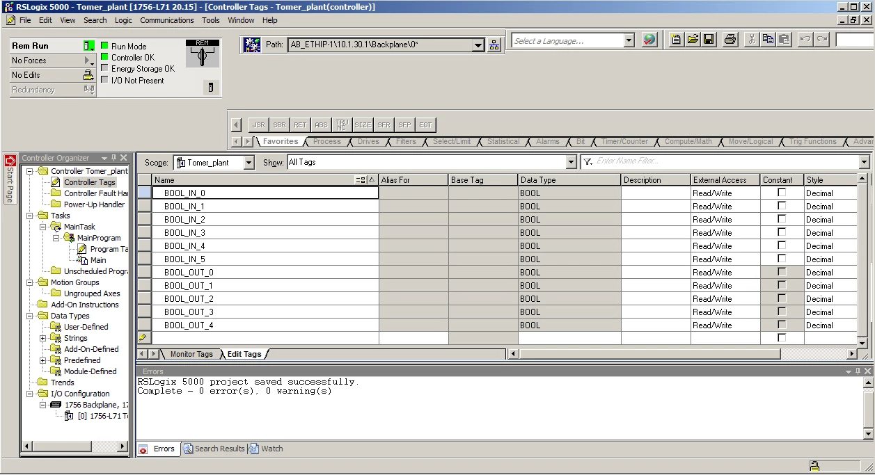
工程工作站的屏幕截图,声明正在使用的控制器标记。
Next we would like to write the actual code/program for our assembly line. Usually, PLCs support a wide range of programming languages/interfaces, including ladder-diagrams and structured text. We chose to write a simple program using ST; this program will be quite simple. It will sequentially bring merchandise pallets to the turntable, which turns 90 degrees, and send the merchandise further on the conveyor belt.
接下来,我们想为我们的装配线编写实际的代码/程序。通常,PLC 支持多种编程语言/接口,包括梯形图和结构化文本。我们选择使用ST编写一个简单的程序;这个程序将非常简单。它将依次将商品托盘带到转盘上,转盘旋转 90 度,并将商品进一步发送到传送带上。
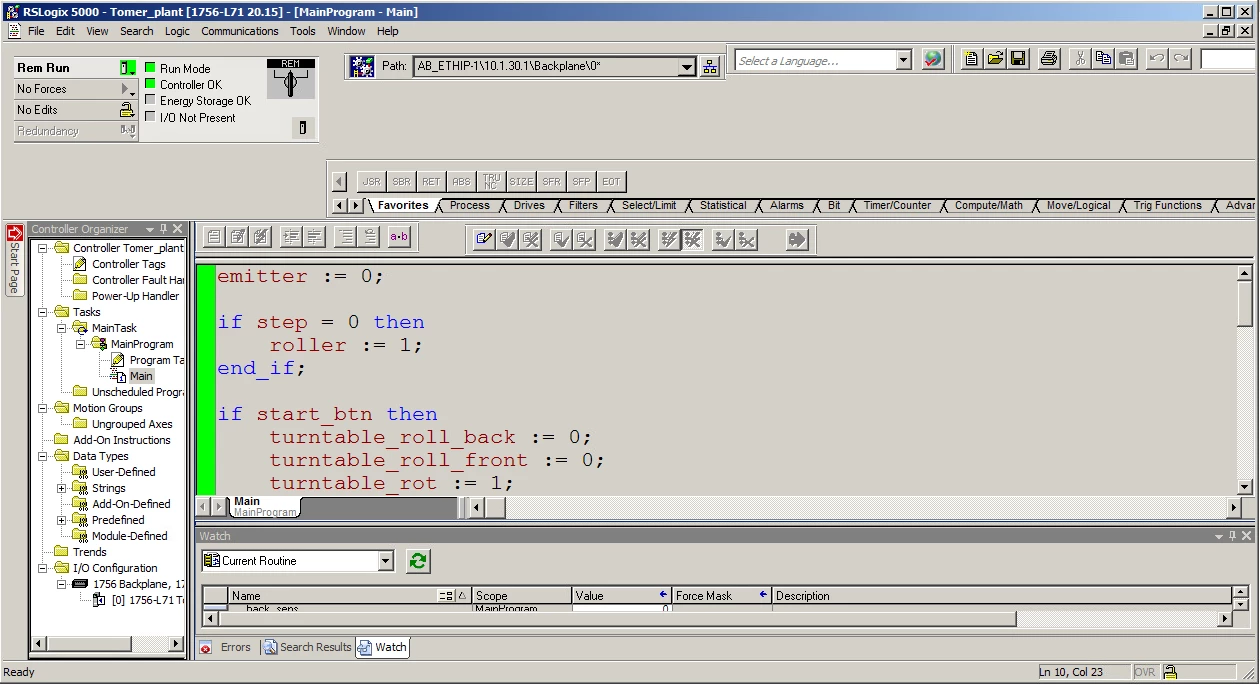
工程工作站上的编程视图的屏幕截图。
After writing the program, we compile and download our project to the PLC. By doing so we modify the logic stored inside the PLC, which modifies its behavior. Now the PLC controls the physical components in our factory, which start transferring merchandise on our assembly line.
编写程序后,我们将项目编译并下载到 PLC。通过这样做,我们修改了存储在 PLC 中的逻辑,从而修改了其行为。现在,PLC控制着我们工厂的物理组件,这些组件开始在我们的装配线上转移商品。

连接到工作PLC时正常运行的装配线。
Setting Up an HMI to Oversee our Virtual Factory
设置 HMI 来监督我们的虚拟工厂
With our PLC programmed, we next need a Human-Machine Interface (HMI) to bridge between the physical machinery on the plant floor and the human operators who have responsibility over the industrial process. This component connects to PLCs and displays their current status in a user interface. In the HMI, we can see alerts indicating different safety concerns, the status of different components, and other views critical to the proper operation of our process. The HMI is critical because it allows safe and efficient operation, and the ability to monitor and control a physical process.
对 PLC 进行编程后,我们接下来需要一个人机界面 (HMI) 来连接工厂车间的物理机械和负责工业过程的人类操作员。该组件连接到 PLC,并在用户界面中显示其当前状态。在 HMI 中,我们可以看到指示不同安全问题的警报、不同组件的状态以及对我们流程正常运行至关重要的其他视图。HMI至关重要,因为它允许安全高效的操作,并能够监视和控制物理过程。
To create our HMI screens, we chose to use Inductive Automation’s Ignition framework. Ignition enables engineers to create any type of monitoring panel they choose, giving them full control over its design, logic, sources, inputs, and outputs. Using their HMI screen, engineers are able to view and monitor the physical process on their production floor.
为了创建我们的 HMI 屏幕,我们选择使用 Inductive Automation 的 Ignition 框架。Ignition 使工程师能够创建他们选择的任何类型的监控面板,使他们能够完全控制其设计、逻辑、源、输入和输出。使用HMI屏幕,工程师能够查看和监控生产车间的物理过程。
In our factory, we will create a panel that counts the number of pallets going through our assembly line. We will start by downloading the Ignition suite locally and setting up a local account.
在我们的工厂中,我们将创建一个面板来计算通过我们装配线的托盘数量。我们将首先在本地下载 Ignition 套件并设置一个本地帐户。
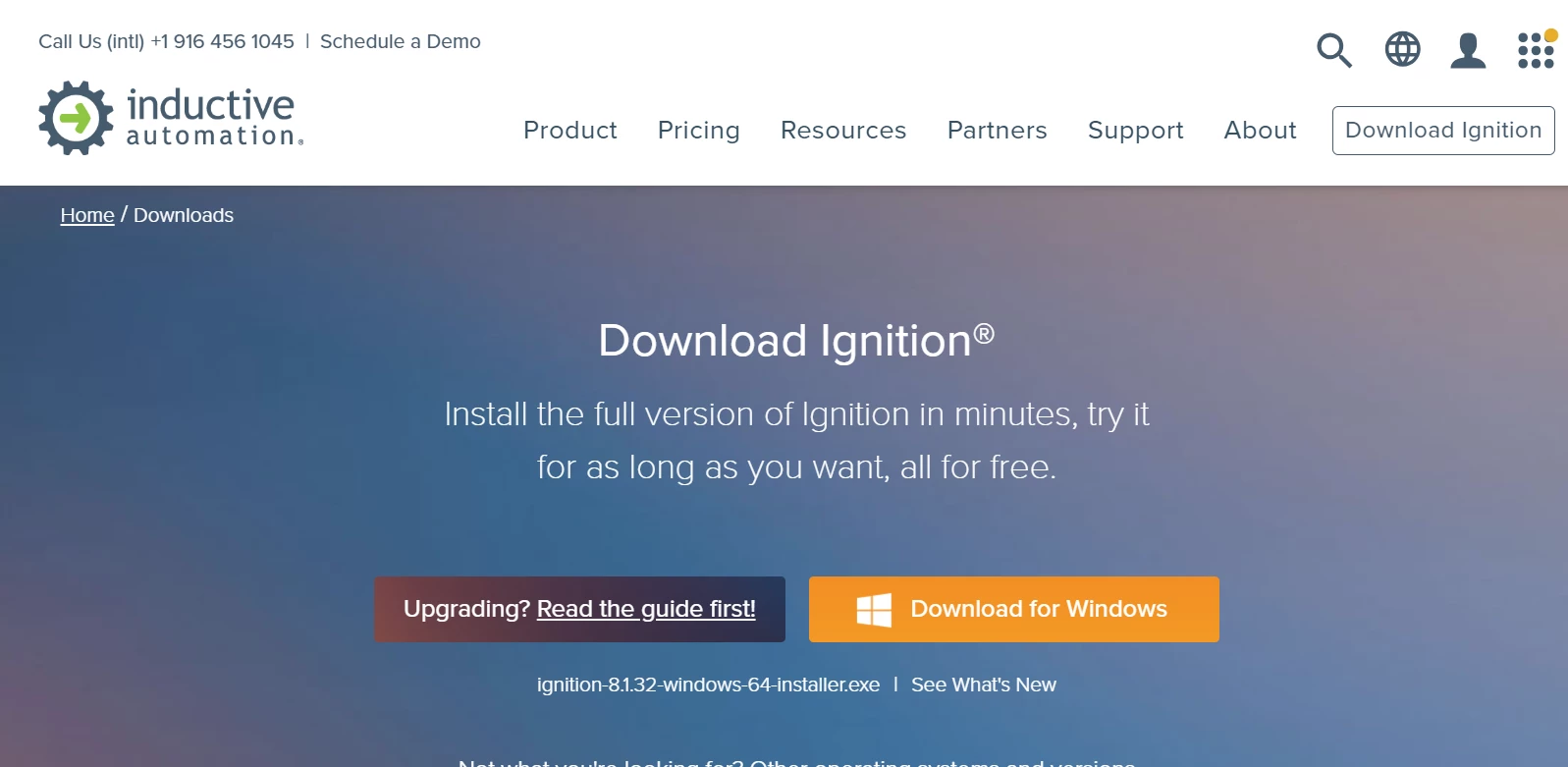
点火框架软件安装页面的屏幕截图。
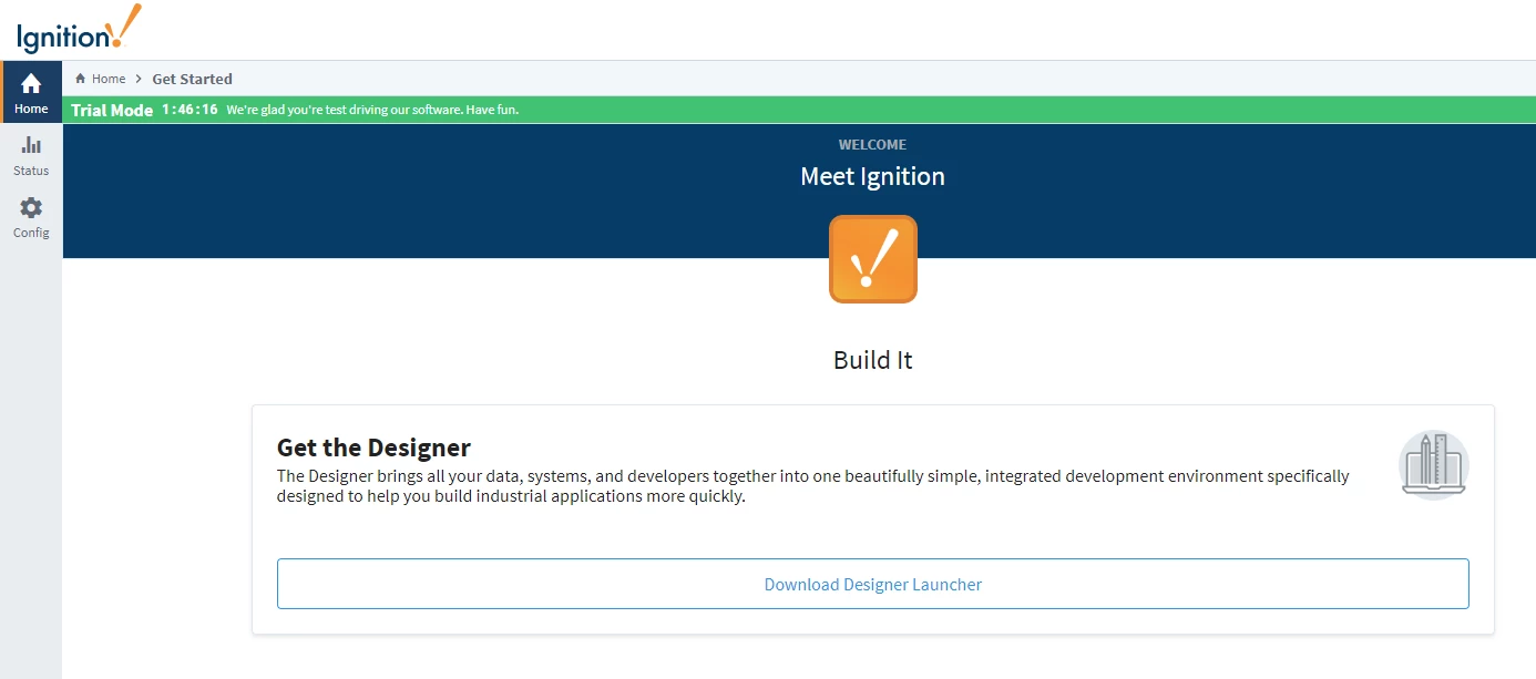
After downloading the framework, we start the Ignition gateway software by opening the management panel using a browser and accessing http://localhost:8088. This gives us access to Ignition’s control server, allowing us to start configuring our HMI project.
下载框架后,我们通过使用浏览器打开管理面板并访问 http://localhost:8088 .这使我们能够访问 Ignition 的控制服务器,从而开始配置我们的 HMI 项目。
First, we connect Ignition to the PLC over CIP on port 44818.
首先,我们通过端口 44818 上的 CIP 将 Ignition 连接到 PLC。
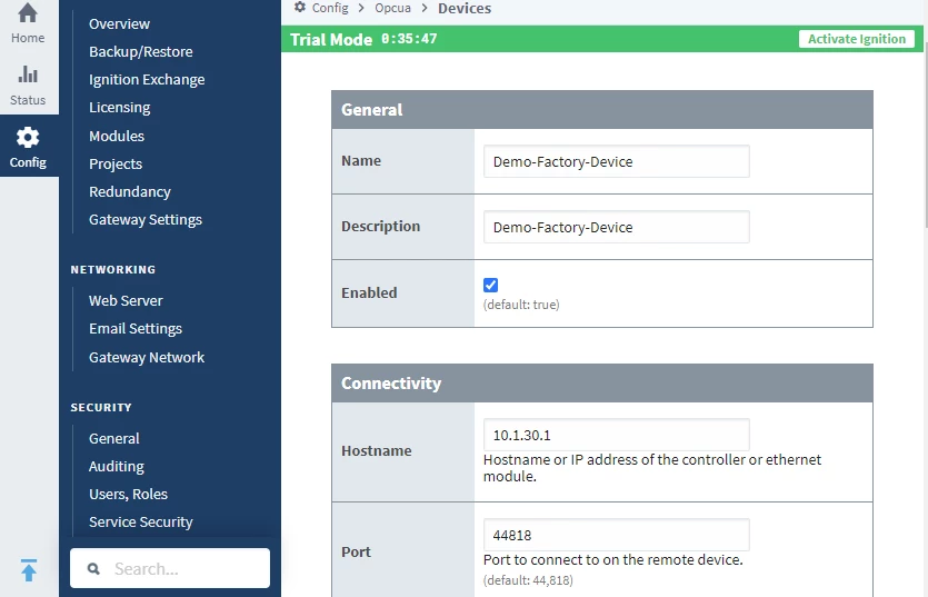
我们特定 PLC 连接的配置截图。
Ignition has many drivers that communicate with different PLCs; in our case, a CIP driver connects to our PLC. Meanwhile a local OPC UA server (managed by the Ignition gateway software) externalizes an interface to our PLC. This OPC UA server will be used later by our HMI. Read more about OPC UA in our OPC UA Deep Dive Series.
Ignition 有许多与不同 PLC 通信的驱动器;在我们的例子中,CIP 驱动程序连接到我们的 PLC。同时,本地 OPC UA 服务器(由 Ignition 网关软件管理)将接口外部化到 PLC。此 OPC UA 服务器稍后将由我们的 HMI 使用。在我们的 OPC UA 深入探讨系列中阅读更多关于 OPC UA 的信息。
Designing an HMI Panel 设计 HMI 面板
Next we download the Ignition designer application from the local Ignition web interface. This will help us design the UI for the HMI and create event-driven scripts to display our factory’s status.
接下来,我们从本地 Ignition Web 界面下载 Ignition 设计器应用程序。这将帮助我们设计 HMI 的 UI,并创建事件驱动的脚本来显示我们工厂的状态。
设计器应用程序的下载页面的屏幕截图。
Using the designer application, we can start building our HMI view, which will contain a gauge counting the number of pallets moving in our assembly line. To implement this, we create a memory tag that holds the amount value of pallets in our factory.
使用设计器应用程序,我们可以开始构建我们的 HMI 视图,其中将包含一个仪表,用于计算装配线上移动的托盘数量。为了实现这一点,我们创建了一个内存标签,用于保存我们工厂中托盘的数量值。
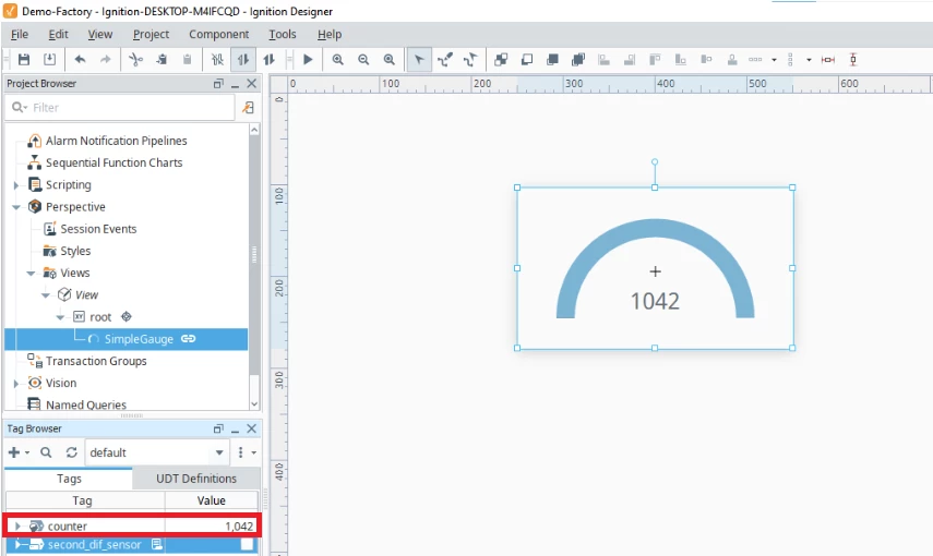
显示我们创建的视图的编辑器界面;计数器内存标签在左下角突出显示。
We want this tag to be incremented each time the second_dif_sensor is on. To implement this feature we create a simple python script that is invoked each time a sensor value change event occurs.
我们希望每次打开时 second_dif_sensor 都会递增此标记。为了实现此功能,我们创建了一个简单的 python 脚本,每次发生传感器值更改事件时都会调用该脚本。
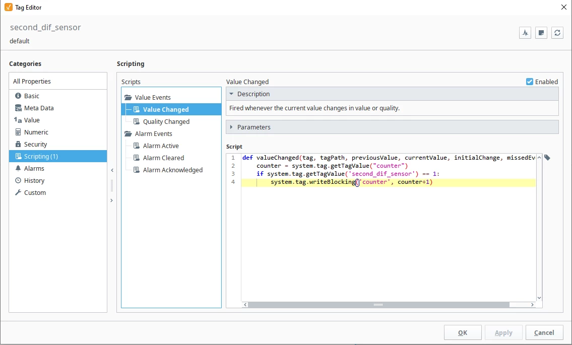
扩散传感器“值已更改”事件的脚本视图。
After saving our project we can open the HMI perspective from the web browser and monitor the industrial process in our virtual factory.
保存项目后,我们可以从 Web 浏览器打开 HMI 透视图,并在我们的虚拟工厂中监控工业过程。
Completing Our Industrial Playground
完善我们的工业游乐场
Our factory has come together and operates as expected, all the components have been set. Now we can start thinking about what could go wrong in such a factory. As illustrated below, our physical components are connected to the PLC using the CIP protocol connection maintained by Factory/IO’s own drivers. The PLC is set up by downloading the logic for operation from the EWS using the RSLogix5000 software; this is done also over CIP communication. Finally, the Ignition CIP client communicates with the PLC and externalizes an OPC UA server to supply live feed of the PLC state for monitoring on the HMI.
我们的工厂已经聚集在一起并按预期运行,所有组件都已设置好。现在我们可以开始思考这样的工厂可能出什么问题了。如下图所示,我们的物理组件使用 Factory/IO 自己的驱动程序维护的 CIP 协议连接连接到 PLC。通过使用 RSLogix5000 软件从 EWS 下载操作逻辑来设置 PLC;这也是通过CIP通信完成的。最后,Ignition CIP 客户端与 PLC 通信,并将 OPC UA 服务器外部化,以提供 PLC 状态的实时馈送,以便在 HMI 上进行监控。
In part two of this series, we will explain and demonstrate some practical and theoretical attacks against factories that defenders should understand and manage risk around. This will be particularly valuable for IT security staff newly responsible for OT, a trend picking up traction within enterprises where cyber-physical systems are prevalent.
在本系列的第二部分中,我们将解释和演示一些针对工厂的实践和理论攻击,防御者应该了解和管理周围的风险。这对于新负责 OT 的 IT 安全人员来说尤其有价值,这一趋势在网络物理系统盛行的企业中越来越受欢迎。
原文始发于Tomer Goldschmidt:Threat Modeling Industrial Environments Using A Virtual Factory (Part 1)
转载请注明:Threat Modeling Industrial Environments Using A Virtual Factory (Part 1) | CTF导航