
Sometimes you need to get in the way of a hardware device and its controller, and see what it has to say for itself. If you are lucky, the two parts are communicating using a serial port, and then it’s relatively simple to do. In this post, I will explain two scenarios where I had to do this, and the approach that I took in each. As a bonus, I’ll also show some hardware that I put together to make it easier.
有时你需要妨碍硬件设备及其控制器,看看它自己要说什么。如果幸运的话,这两个部分是使用串口进行通信的,然后做起来就比较简单了。在这篇文章中,我将解释我必须这样做的两种情况,以及我在每种情况下采取的方法。作为奖励,我还将展示一些我放在一起的硬件,以使其更容易。
Scenario 1: IoT authorisation dongle
场景 1:IoT 授权加密狗
In this scenario, I was trying to connect to an IoT device. This particular device listened for a specific WiFi SSID beacon, then tried to connect with a calculated PSK. The calculation was performed on a PC, but required a connected dongle to provide part of the calculation. Unplugging the dongle from the controller PC, and plugging it into my own computer’s USB port, I could see that it enumerated as an FTDI serial device. Keeping in mind that I don’t control the controller PC, and I don’t control the dongle, what do?
在此方案中,我尝试连接到 IoT 设备。此特定设备侦听特定的WiFi SSID信标,然后尝试与计算出的PSK连接。计算是在 PC 上执行的,但需要连接的加密狗来提供部分计算。从控制器 PC 上拔下加密狗,并将其插入我自己计算机的 USB 端口,我可以看到它枚举为 FTDI 串行设备。请记住,我不控制控制器 PC,也不控制加密狗,该怎么办?
Fortunately, I happened to have another FTDI USB Serial cable with me, that enumerated sufficiently similar to the dongle that the controller software was happy to talk to it. That gets me a third of the way there!
幸运的是,我碰巧随身携带了另一根FTDI USB串行电缆,该电缆枚举与加密狗非常相似,控制器软件很乐意与之通信。这让我走了三分之一的路!
This is actually quite a valuable technique – present a device to the controller that looks sufficiently similar to what it is expecting that it will use it, but that we can see what it is doing. There are a couple of things to keep in mind, though. For some devices, you can update the VendorID:ProductID that is stored in EEPROM so that it matches the real device. e.g. using ftdi_eeprom on Linux. However, it will use the driver associated with that VID:PID to talk to it! So, you probably won’t be successful making a PL2303 serial device report itself as an FTDI serial device, because they use different drivers. In fact, I once managed to make an ATM bluescreen itself by making a Linux Serial Gadget report itself as an FTDI device! Nonetheless, since FTDI devices in particular have reprogrammable EEPROMs, it’s not unusual for device manufacturers to customise the VID:PID to make them uniquely identifiable, even if they still use the generic FTDI driver. You can then do the same using freely available tools, if you have a suitable substitute to hand.
这实际上是一种非常有价值的技术——向控制器展示一个看起来与它期望使用它的设备非常相似的设备,但我们可以看到它在做什么。不过,有几件事需要牢记。对于某些设备,您可以更新存储在 EEPROM 中的 VendorID:ProductID,使其与真实设备匹配。例如,在 Linux 上使用 ftdi_eeprom。但是,它将使用与该 VID:PID 关联的驱动程序与其通信!因此,您可能无法成功使 PL2303 串行设备将自己报告为 FTDI 串行设备,因为它们使用不同的驱动程序。事实上,我曾经设法通过使 Linux Serial Gadget 将自己报告为 FTDI 设备来制作 ATM 蓝屏!尽管如此,由于 FTDI 器件尤其具有可重新编程的 EEPROM,因此设备制造商定制 VID:PID 以使其具有唯一可识别性并不罕见,即使他们仍然使用通用 FTDI 驱动程序。然后,如果您手头有合适的替代品,您可以使用免费提供的工具做同样的事情。
The next step was seeing what the controller was saying to the serial cable. Fortunately, I had a second USB Serial cable with me, so I could get the data back into a PC (well, device running Linux, anyway!). I connected the TX of one cable to the RX of the other, and vice versa, and connected the two Ground pins together. Then I could use a serial terminal program like picocom to see what the controller was sending, and try to figure out the baud rate. Note that the second USB Serial cable didn’t have to be an FTDI specifically, since it was only the controller PC that cared what sort of device it was talking to.
下一步是查看控制器对串行电缆说了什么。幸运的是,我随身携带了第二根 USB 串行电缆,因此我可以将数据传回 PC(好吧,无论如何,运行 Linux 的设备!我将一根电缆的TX连接到另一根电缆的RX,反之亦然,并将两个接地引脚连接在一起。然后,我可以使用像 picocom 这样的串行终端程序来查看控制器发送的内容,并尝试计算波特率。请注意,第二根 USB 串行电缆不必专门是 FTDI,因为只有控制器 PC 才关心它正在与哪种设备通信。
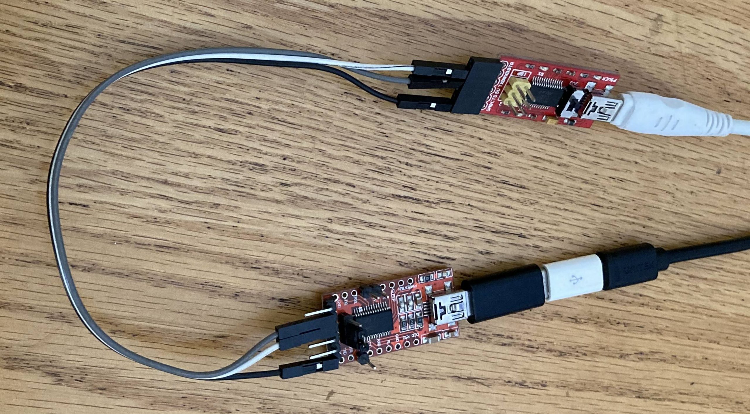
两个 FTDI USB-UART 适配器配置在交叉配置中。
I ran the controller program a few times while looking at the serial terminal emulator, and changed the baud rate until what I saw seemed reasonable. Unsurprisingly, the correct baud rate turned out to be 115200, probably the most common rate for relatively modern devices. Older devices with low bandwidth requirements will often stick with 9600 baud. 2/3rds of the way there!
我在查看串行终端仿真器时运行了几次控制器程序,并更改了波特率,直到我看到的看起来合理为止。不出所料,正确的波特率竟然是 115200,这可能是相对现代设备最常见的波特率。带宽要求较低的旧设备通常会坚持使用 9600 波特。2/3的路程!
Of course, seeing the initial conversation attempts with the controller application doesn’t really get you too far, without being able to respond with the data it is expecting. I plugged the dongle into my Linux PC as well, so I could relay the data that the controller was sending to the real dongle.
当然,看到与控制器应用程序的初始对话尝试并不会让你走得太远,因为无法用它所期望的数据进行响应。我还将加密狗插入我的 Linux PC,这样我就可以将控制器发送的数据中继到真正的加密狗。
socat -x /dev/ttyUSB0,raw,echo=0,b115200 /dev/ttyUSB1,raw,echo=0,b115200 2>&1 | tee serial.logBreaking that down, socat is the swiss army knife of forwarders, and the -x option tells it to dump whatever it forwards in hex format. The two following arguments are the source and destination, in this case the device /dev/ttyUSB0 or ttyUSB1, doing no processing of the data (“raw”), and not echoing any data it receives to the original sender. (An echo can be useful for a cli, so the person typing can see what they have typed, but it is not useful for a machine that is not expecting it.) The hex dump output is then logged in serial.log where we can review it later, but also printed to the screen, so we can see that data is actually passing in both directions.
分解一下,socat 是转发器的瑞士军刀,-x 选项告诉它以十六进制格式转储它转发的任何内容。以下两个参数是源和目标,在本例中为设备 /dev/ttyUSB0 或 ttyUSB1,不处理数据(“原始”),并且不将其接收的任何数据回显给原始发送方。(echo 对于 cli 很有用,因此键入的人可以看到他们键入的内容,但对于不需要它的计算机来说,它没有用。然后将十六进制转储输出记录在serial.log,以便我们稍后查看它,但也打印到屏幕上,因此我们可以看到数据实际上是在两个方向上传递的。
With that running, I queried the controller program to discover the PSK for the IoT device, and was able to capture the conversation with the dongle. From there, it becomes an exercise in reverse engineering the protocol, and trying to make sense of it. In this case, I was ultimately unsuccessful, as it was a binary protocol, I didn’t have a lot of time, and this wasn’t really a focus of my assessment anyway.
运行后,我查询了控制器程序以发现物联网设备的 PSK,并能够捕获与加密狗的对话。从那里开始,它变成了对协议进行逆向工程的练习,并试图理解它。在这种情况下,我最终没有成功,因为它是一个二进制协议,我没有很多时间,无论如何这都不是我评估的重点。
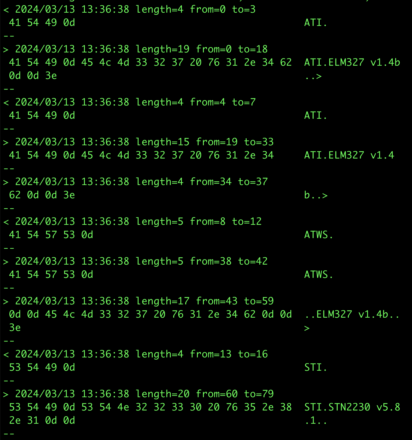
使用相同技术拦截 Forscan 与 ELM327 加密狗通信的示例输出。这是通过互联网中继 socat 连接来完成的,因为这是可能的,也因为我没有随身携带加密狗。在这种情况下,固定波特率成为一个问题,因为 Forscan 试图在可能的情况下升级波特率,而 socat 无法处理这个问题。更新 Forscan 配置以不更改波特率允许它工作,尽管比直接连接慢。
One tool I did end up writing was a script to coalesce multiple consecutive socat -x reports within a specified timeframe into a single report, as well as changing the direction markers (< >) into a useful text description. This can make it easier to make sense of data reported by socat. That script can be found here.
我最终编写的一个工具是一个脚本,用于将指定时间范围内的多个连续 socat -x 报告合并为单个报告,并将方向标记 (< >) 更改为有用的文本描述。这样可以更容易地理解 socat 报告的数据。该脚本可以在此处找到。
Alternative approaches I considered:
我考虑的替代方法:
- Since this was actually serial over USB, I could use USBProxy to make my Linux device (which had a USB Device Controller) emulate the real USB dongle, and allow me to capture the data relayed between the two. This would be simpler, as it would not require the two USB Serial cables. This is the ultimate example of “presenting a similar looking device”, because it simply copies the target device’s descriptors and presents those to the host.
由于这实际上是通过 USB 串行的,因此我可以使用 USBProxy 使我的 Linux 设备(具有 USB 设备控制器)模拟真正的 USB 加密狗,并允许我捕获两者之间中继的数据。这将更简单,因为它不需要两根 USB 串行电缆。这是“呈现外观相似的设备”的终极示例,因为它只是复制目标设备的描述符并将其呈现给主机。
This is an option, but I have not actually had the best of luck with USBProxy, and would have had to figure out how to decapsulate the serial data from the USB packets.
这是一个选项,但我实际上并没有在 USBProxy 上遇到最好的运气,并且必须弄清楚如何从 USB 数据包中解封装串行数据。 - Open up the dongle and try to tap the RX and TX pins after the FTDI USB-Serial chip.
打开加密狗并尝试点击 FTDI USB-Serial 芯片后面的 RX 和 TX 引脚。
Since the dongle was acting as an HSM (Hardware Security Module), I was concerned that opening it up might trigger tamper-detection measures, and wipe out the dongle. That would not have endeared me to the client!
由于加密狗充当 HSM(硬件安全模块),我担心打开它可能会触发篡改检测措施,并清除加密狗。那不会让我受到客户的喜爱!
Scenario 2: Industrial device talking to its controller
场景 2:工业设备与其控制器通信
In this specific scenario, I had a WiFi dongle connecting an electrical inverter to a cloud service. The dongle had a DE9 port through which it communicated with the inverter. This is strongly suggestive of an RS232 connection, as this has been a common connector for at least 30 years, along with the DE25, for talking to modems, etc.
在这个特定场景中,我有一个 WiFi 加密狗将逆变器连接到云服务。加密狗有一个 DE9 端口,通过该端口与逆变器通信。这强烈暗示了 RS232 连接,因为它与 DE25 一起成为至少 30 年的通用连接器,用于与调制解调器等通信。
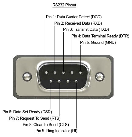
DE9 引脚排列,包括硬件流量控制引脚
In order to expose the pins, I purchased two DE9 breakout boards, one with a female connector, and the other with a male connector. I then used some long header pins to connect them back to back, so that each signal was connected straight through. I also soldered some header pins to facilitate adding extra connections to the signals.
为了暴露引脚,我购买了两块 DE9 分线板,一块带母连接器,另一块带公连接器。然后,我使用一些长接头引脚将它们背靠背连接,以便每个信号都直接连接。我还焊接了一些针座引脚,以便于向信号添加额外的连接。
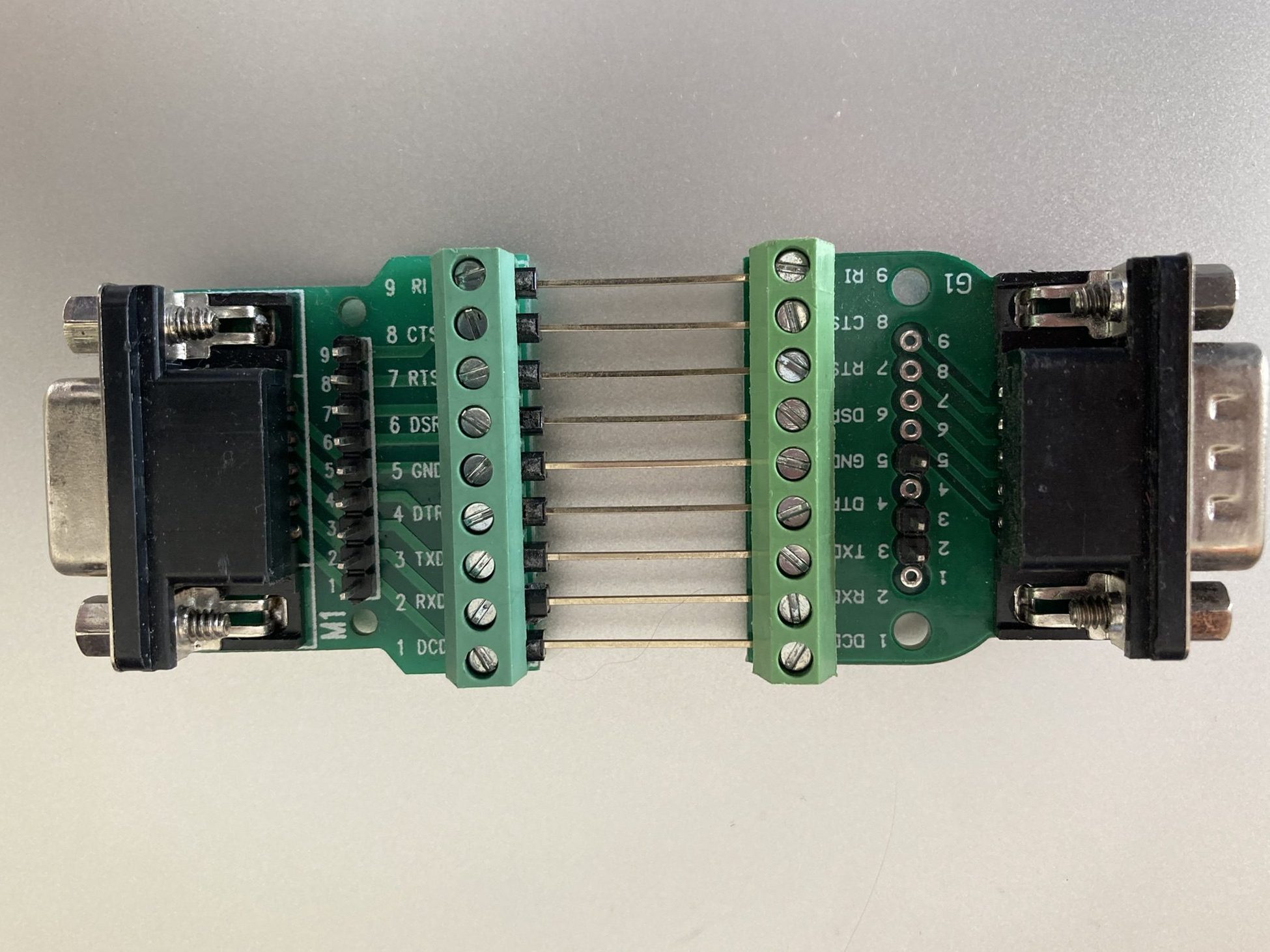
背靠背的公头和母头 DE9 分线板。
Connecting this in between the inverter and the dongle, I used a multimeter to check whether this was indeed using the standard DE9 RS232 pinout. It was, with the additional detail that it was using the Ring Indicator pin (pin 9) to power the dongle at 12V. I thought this was quite a clever use of the pin, because the standard does not provide for power to be provided over the cable, but any compliant device connected to the port would be expected to handle 12V anyway. It turns out that this is a fairly common thing, with the serial ports on an industrial motherboard I looked at recently having the option to provide 12V or 5V on this pin.
在逆变器和加密狗之间连接它,我使用万用表检查这是否确实使用了标准的 DE9 RS232 引脚排列。另外,它使用环形指示器引脚(引脚 9)在 12V 下为加密狗供电。我认为这是对引脚的巧妙使用,因为该标准没有规定通过电缆提供电源,但任何连接到端口的兼容设备都有望处理 12V。事实证明,这是一件相当普遍的事情,我最近看到的工业主板上的串行端口可以选择在此引脚上提供 12V 或 5V。
Keeping in mind that there are two transmit lines in operation (one in each direction), to capture the data sent between the dongle and the inverter, I would need two USB-RS232 cables in order to have two receive pins. Note that since the voltage levels are different to the TTL levels used by my USB-Serial cables in the previous scenario, and would destroy cables not designed for such voltages, I could not reuse those cables. To enable me to sniff the traffic between the two devices, I connected only the RX and ground pins of each USB-RS232 cable to the two data pins (pin 2 and 3), and the ground pin of the breakout boards.
请记住,有两条传输线在运行(每个方向一条),要捕获加密狗和逆变器之间发送的数据,我需要两根 USB-RS232 电缆才能有两个接收引脚。请注意,由于电压电平与我的 USB 串行电缆在上一个场景中使用的 TTL 电平不同,并且会损坏不是为此类电压设计的电缆,因此我无法重复使用这些电缆。为了能够嗅探两个设备之间的流量,我只将每根 USB-RS232 电缆的 RX 和接地引脚连接到两个数据引脚(引脚 2 和 3)以及分支板的接地引脚。
Note that RS232 and TTL Serial specifies Rx and Tx from the perspective of the closest device normally, so a pin on a microcontroller labelled TX would mean that the microcontroller would transmit on that pin, but the device connecting to it would receive those transmissions. i.e. connections are crossed over.
请注意,RS232 和 TTL 串行通常从最近的设备的角度指定 Rx 和 Tx,因此微控制器上标记为 TX 的引脚意味着微控制器将在该引脚上传输,但连接到它的设备将接收这些传输。即连接交叉。
In this case, I had two independent serial ports, /dev/ttyUSB0 and /dev/ttyUSB1 that did not need to be connected to each other as we did in the previous scenario, because the TX lines were not connected to anything. So, we can run two independent instances of socat to record the data from each one (in different terminals):
在本例中,我有两个独立的串行端口,/dev/ttyUSB0 和 /dev/ttyUSB1,它们不需要像在上一个场景中那样相互连接,因为 TX 线没有连接到任何东西。因此,我们可以运行两个独立的 socat 实例来记录每个实例的数据(在不同的终端中):
socat -x /dev/ttyUSB0,raw,echo=0,b9600 - > /dev/null 2>&1 | tee serial0.log
socat -x /dev/ttyUSB1,raw,echo=0,b9600 - > /dev/null 2>&1 | tee serial1.log
The problem with this is that it becomes difficult to view the data in context. i.e. one end sent X, and the other end responded with Y. Apart from anything else, socat records data read with the same directional notation, so merging the files means you can’t tell which serial port read what. In order to solve that, we can actually use the same command line from the previous scenario, in order to record the timing and direction of the data as it was seen.
这样做的问题是很难在上下文中查看数据。即一端发送 X,另一端以 Y 响应。 除此之外,socat 记录以相同方向符号读取的数据,因此合并文件意味着您无法分辨哪个串行端口读取了什么。为了解决这个问题,我们实际上可以使用与上一个场景相同的命令行,以记录所看到的数据的时间和方向。
socat -x /dev/ttyUSB0,raw,echo=0,b9600 /dev/ttyUSB1,raw,echo=0,b9600 2>&1 | tee serial.logData transmitted through a serial port that has no listener on the other end, simply disappears. There is no timeout, no full buffer, no confirmation of reception.
通过另一端没有侦听器的串行端口传输的数据会消失。没有超时,没有完全缓冲区,没有接收确认。

如果一个串口传输,没有人监听,它甚至发生了吗?
This is a slightly different configuration of the listening serial cables, which has two major implications:
这是侦听串行电缆的配置略有不同,它有两个主要含义:
- Because the TX pins of the intercepting USB-Serial adapters are not connected, it is not actually a fully-featured Person in the Middle. Yes, you can snoop on the data going in each direction, but you cannot change it. The TX pin of each device is directly connected to the RX pin of the other device.
由于拦截 USB-Serial 适配器的 TX 引脚未连接,因此它实际上并不是功能齐全的中间人。是的,您可以窥探每个方向的数据,但不能更改它。每个器件的 TX 引脚直接连接到另一个器件的 RX 引脚。
This should actually be more reliable than setting up the full Person in the Middle, as that introduces additional latency, while socat reads from one serial port, and writes to the other. For a protocol that is very latency sensitive, this might be enough to stop it working correctly.
这实际上应该比设置完整的中间人更可靠,因为这会引入额外的延迟,而 socat 从一个串行端口读取,然后写入另一个串行端口。对于对延迟非常敏感的协议,这可能足以阻止其正常工作。 - Additionally, the DE9 connection has extra pins, which may be used for handshaking (DSR, DTR, CTS, RTS), and the timings of those transitions when passed directly through might not match after the additional socat latency. Note: socat is unable to pass through handshaking signals at the same time as forwarding the data bytes.
Fortunately, hardware handshaking is less commonly used these days, as devices are generally fast enough to process data at most common baud rates, without having to tell the other end to stop sending.
Can we turn this into a fully featured PitM? Yes, with a caveat. By disconnecting the header pins between the RX and TX pins, and connecting those in crossover form to the two USB-RS232 dongles, we can end up with a full PitM. As before, we can use the same socat command line as the first scenario to record the data.
我们能把它变成一个功能齐全的 PitM 吗?是的,但需要注意。通过断开 RX 和 TX 引脚之间的接头引脚,并将其交叉形式连接到两个 USB-RS232 加密狗,我们最终可以得到一个完整的 PitM。和以前一样,我们可以使用与第一个场景相同的 socat 命令行来记录数据。
But what happens when we actually do want to tamper with the data? Well, one big hammer approach is to put Mallet to work:
但是,当我们真的想篡改数据时会发生什么?好吧,一个大锤子的方法是让 Mallet 工作:
socat TCP-LISTEN:1234,reuseaddr /dev/ttyUSB0,raw,echo=0,b9600 &

socat /dev/ttyUSB1,raw,echo=0,b9600 SOCKS:127.0.0.1:localhost:1234,socksport=1080
This routes any data from USB1 via a SOCKS connection to where Mallet is listening (127.0.0.1:1080), and asks Mallet to connect to the socat instance on localhost:1234, which will relay the data to USB0, and vice versa. With that, you now have access to all the tools that Mallet offers.
这会通过 SOCKS 连接将来自 USB1 的任何数据路由到 Mallet 正在侦听的位置 (127.0.0.1:1080),并要求 Mallet 连接到 localhost:1234 上的 socat 实例,该实例会将数据中继到 USB0,反之亦然。有了它,您现在可以访问 Mallet 提供的所有工具。
But that is quite a big hammer. Unfortunately, Mallet is not yet as easy to use as I would like. It may also be possible to do some modifications using tools such as netsed, or similar.
但这是一把大锤子。不幸的是,Mallet 还没有我想要的那么容易使用。也可以使用网络化或类似工具进行一些修改。
Building custom hardware
构建自定义硬件
Another approach that “does away” with the computer in the middle is to shrink that computer dramatically, down to an ESP32. The ESP32 is a really powerful little microcontroller, that happens to have 3 serial ports available. Perfect for a task like this, with one left over for logging. Of course, we can also log over the network, since the ESP32 has WiFi. The nice thing about using a separate board is that it can be nice to be able to place them somewhere awkward to work (e.g. on the factory floor), and then access them remotely over the network. The ESP32 can even run Wireguard, for the ultimate in secure remote access.
另一种“消除”中间计算机的方法是将计算机大幅缩小,缩小到 ESP32。ESP32 是一款非常强大的小型微控制器,恰好有 3 个串口可用。非常适合这样的任务,剩下的一个用于日志记录。当然,我们也可以通过网络登录,因为 ESP32 有 WiFi。使用单独的电路板的好处是,能够将它们放置在难以工作的地方(例如在工厂车间),然后通过网络远程访问它们会很好。ESP32 甚至可以运行 Wireguard,实现终极安全的远程访问。
I spent some time making a custom board for the job, based on an SP3232 RS232 transceiver. This transceiver has two input channels, and two output channels, which lines up nicely with the two serial ports. I suspect that they were originally intended to manage a pair of hardware handshaking pins alongside the usual RX and TX, but they work perfectly in this role too.
我花了一些时间为这项工作制作了一个基于SP3232 RS232收发器的定制板。该收发器有两个输入通道和两个输出通道,与两个串行端口很好地对齐。我怀疑它们最初的目的是在通常的 RX 和 TX 旁边管理一对硬件握手引脚,但它们在这个角色中也能完美工作。
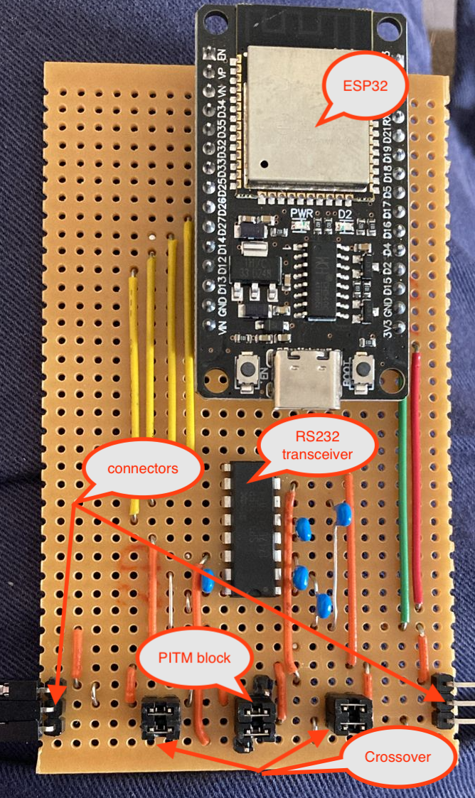
带有 RS232 收发器的定制 ESP32 载板,以及用于调整各种连接的跳线接头
The serial devices connect to the pins marked as connectors, on the bottom left and right of the board. The upper of the 3 connector pins is Ground, the middle pin is TX from the left to RX on the right, and the bottom pin is TX from the right to RX on the left. They don’t strictly have to be connected that way, if all you are doing is snooping, as there is an RX pin connected to both “rails”, and you can see the traffic in either direction anyway. It can be a bit tricky to figure out which end the traffic reported comes from, though!
串行器件连接到电路板左下角和右下角标记为连接器的引脚。3 个连接器引脚的上部是 Ground,中间引脚是从左边到 RX 的 TX,底部引脚是从右边到 RX 的 TX。如果您所做的只是窥探,它们不必严格地以这种方式连接,因为有一个 RX 引脚连接到两个“轨道”,无论如何您都可以看到任一方向的流量。但是,要弄清楚报告的流量来自哪一端可能有点棘手!
It is also possible to swap RX and TX on either side, by changing the jumpers on the “Crossover” block on either side from horizontal to vertical.
也可以通过将两侧“Crossover”块上的跳线从水平更改为垂直来交换任一侧的 RX 和 TX。
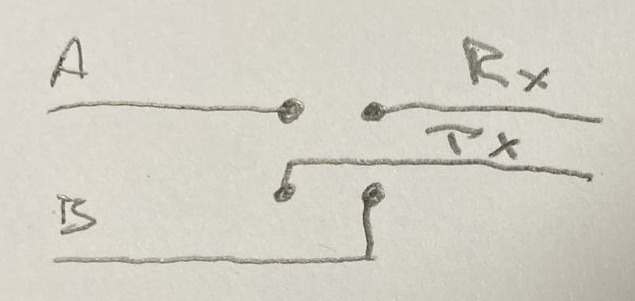
水平跳线将 A 连接到 Rx,将 B 连接到 Tx,垂直跳线将 A 连接到 Tx,B 连接到 Rx。
To select between Snoop or PitM, change the jumpers on the PitM block from horizontal to vertical, connecting to the additional pin adjacent to the block of 4 on either side. This pin is the TX from each serial port on the ESP32, via the RS232 transceiver, and allows the ESP32 to transmit something other than what was received.
要在 Snoop 或 PitM 之间进行选择,请将 PitM 块上的跳线从水平更改为垂直,连接到两侧与 4 块相邻的附加销钉。该引脚是通过 RS232 收发器从 ESP32 上的每个串口发送的 TX,并允许 ESP32 传输接收到的内容以外的内容。
The following is an extremely barebones Arduino example of how the ESP32 can copy or tamper data from one serial port to another:
下面是一个非常准系统的 Arduino 示例,说明 ESP32 如何将数据从一个串口复制或篡改到另一个串口:
void setup() {
  Serial1.begin(115200, SERIAL_8N1, RXD1, TXD1);
  Serial2.begin(115200, SERIAL_8N1, RXD2, TXD2);
}

void loop() {
  uint8_t c;
  if (Serial1.available()) {
    c = Serial1.read();
    if (c == 'a') c = 'b';
    Serial2.write(c);
  }

  if (Serial2.available()) {
    c = Serial2.read();
    Serial1.write(c);
  }
}
Of course, nobody wants to write code for a microcontroller from scratch. I have found the ESPHome project to be an excellent foundation for this sort of project, even if it is not really how it is intended to be used. It provides features such as WiFi connection management, Over The Air updates, logging over WiFi, Serial port buffering, and a whole lot more. The linked YAML file results in a firmware which can be flashed to the ESP32, that includes all the above features. The below snippet shows the critical parts:
uart:
  - id: uart_bus1
    rx_pin: GPIO25
    tx_pin: GPIO26
    baud_rate: 9600
    debug:
      direction: BOTH
      dummy_receiver: false

  - id: uart_bus2
    rx_pin: GPIO14
    tx_pin: GPIO27
    baud_rate: 9600
#    debug:
#      direction: RX
#      dummy_receiver: false

#stream_server:
#  - uart_id: uart_bus1
#    port: 2001
#
#  - uart_id: uart_bus2
#    port: 2002

uart_mitm:
  uart1: uart_bus1
  uart2: uart_bus2
The main nodes of the above YAML are the uart: node and the uart_mitm: node. The uart: node defines the details of the serial ports, in particular, the baud rate that is to be used, and the uart_mitm: node links the two serial ports together. The other interesting part is the debug: node, which results in the data being sent in both directions being recorded to the ESPHome log. Again, this is better than recording only data read on both serial ports, because it is difficult to determine which port the data was read on!
上述 YAML 的主要节点是 uart: 节点和 uart_mitm: 节点。 uart: 节点定义串行端口的详细信息,特别是要使用的波特率,节点 uart_mitm: 将两个串行端口链接在一起。另一个有趣的部分是 debug: 节点,它导致双向发送的数据被记录到 ESPHome 日志中。同样,这比只记录两个串行端口上读取的数据要好,因为很难确定数据是在哪个端口上读取的!
This is what the uart_mitm: code does:
这是 uart_mitm: 代码的作用:
void UARTMITM::loop() {
  uint8_t c;
  while (this->uart1_->available()) {
    this->uart1_->read_byte(&c);
    this->uart2_->write_byte(c);
  }
  while (this->uart2_->available()) {
    this->uart2_->read_byte(&c);
    this->uart1_->write_byte(c);
  }
}
Essentially the same as the Arduino sketch above. If needed, the uart_mitm: component can be cloned locally, and modifications made to have it tamper with the traffic as needed. Of course, the new firmware would need to be uploaded to the ESP32 for it to take effect. This can be done Over The Air, for extra convenience.
与上面的Arduino草图基本相同。如果需要,可以在本地克隆 uart_mitm: 组件,并根据需要进行修改以使其篡改流量。当然,新固件需要上传到 ESP32 才能生效。为了更加方便,这可以通过无线方式完成。
As an alternative to doing the tampering on the device, if the timing requirements of the protocol allow it, one can use the commented out stream_server: component instead of the uart_mitm: component. This connects each serial port to a TCP server listening on the specified port. This opens up the opportunity to use a tool such as Mallet again, as in the previous scenario:
作为对设备进行篡改的替代方法,如果协议的时序要求允许,则可以使用注释掉 stream_server: 的组件而不是 uart_mitm: 组件。这会将每个串行端口连接到侦听指定端口的 TCP 服务器。这为再次使用工具(如 Mallet)提供了机会,如前面的场景:
socat TCP:serial-pitm:2001 SOCKS:127.0.0.1:serial-pitm:2002,socksport=1080For more examples of how to debug the uart component in ESPHome, check out the documentation.
有关如何在 ESPHome 中调试 uart 组件的更多示例,请查看文档。
Conclusion 结论
In this post I have shown you some approaches to obtaining serial communications from various devices, by operating in a Person in the Middle position. While the techniques shown are mostly useful in an “observation-only” manner, they can certainly be extended to a full tampering configuration.
在这篇文章中,我向您展示了一些从各种设备获取串行通信的方法,方法是在中间位置操作。虽然所展示的技术大多以“仅观察”的方式有用,但它们当然可以扩展到完全的篡改配置。
In many cases, though, just having an idea of what the conversation looks like will be enough to allow you to craft your own program to talk to the device in question, and start getting responses from it. Once you can do that, any controls implemented in the application can be bypassed. Have fun!
但是,在许多情况下,只要了解对话的样子就足以让您制作自己的程序来与相关设备进行对话,并开始从中获得响应。一旦可以执行此操作,就可以绕过应用程序中实现的任何控件。玩得愉快!
原文始发于Rogan Dawes:Serial PitM