A journey into IoT – Unknown Chinese alarm – Part 4 – Internal communications
Disclaimer: as many other security researchers approaching IoT, I have a background in computer science and I started to work on these subjects with little knowledge about electronics and often with a “YOLO” approach(blame it on an old colleague of mine  ). So, it is definitely possible that many of the things you will read here can be inaccurate or can be done in a much better way, especially with more knowledge in the field. Sorry about that. I take advantage of this disclaimer to add a thing: pay particular attention when you put your hands on electronics, especially when you deal with cheap Chinese devices powered by 220V! Some capacitors can cause serious damages even if the device is not plugged into the electric socket!
Today we will have a look at the ports we discovered in the first article of this blog series in our initial analysis with the device powered off. The ports we discovered were the following:
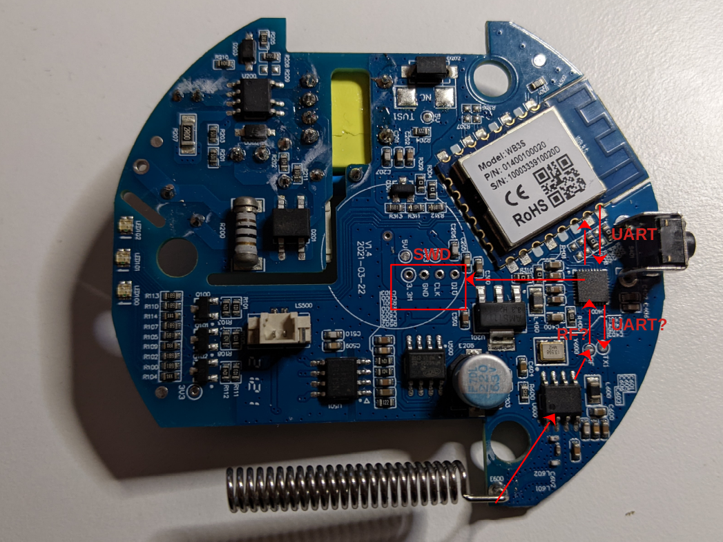
We already analyzed the SWD port in the second article of the series, using that port to dump the firmware. Now we will look at the two potential UART ports and to the unknown port named “RF” on the board.
For this analysis we will use a logic analyzer, a hardware device able to read, show and often interpret digital signals. One of the best choices for this type of instrument is the Saleae Logic Analyzer, that comes with an awesome software able to decode multiple protocols on its own. Depending on the model, the original Saleae Logic Analyzer costs from 400€ to 1200€.
Let’s start to analyze the UART communication port between our main ARM microcontroller and the Tuya WB3S wireless module. The easiest way to sniff communications is to connect the Saleae to the pins of the Tuya module, which are quite large on the board and very easy to reach. The documentation of the module gives us the location of the UART pins:
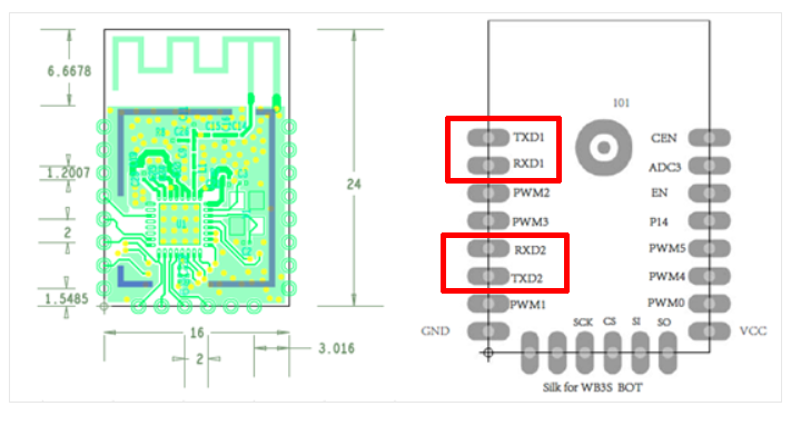
The datasheet shows two serial ports (TXD1-RXD1 and TXD2-RXD2), but according to the documentation the second one should not be available to Tuya customers (but obviously we will verify that).
UART Port 1 – Tuya module and ARM microcontroller
Let’s start with the fist serial port (TXD1-RXD1). During our initial analysis, we hypothesized that this would be some kind of communication port between the main ARM micro-controller and the WiFi Tuya chip.
To sniff communications we need to connect the logic analyzer to the pins of the serial UART port. A quick solution that does not require soldering is to use specific probes. At the office we have a great kit of hands-free probes by SensePeek, but when working on this project I was at home and I had only a basic Chinese BDM frame:
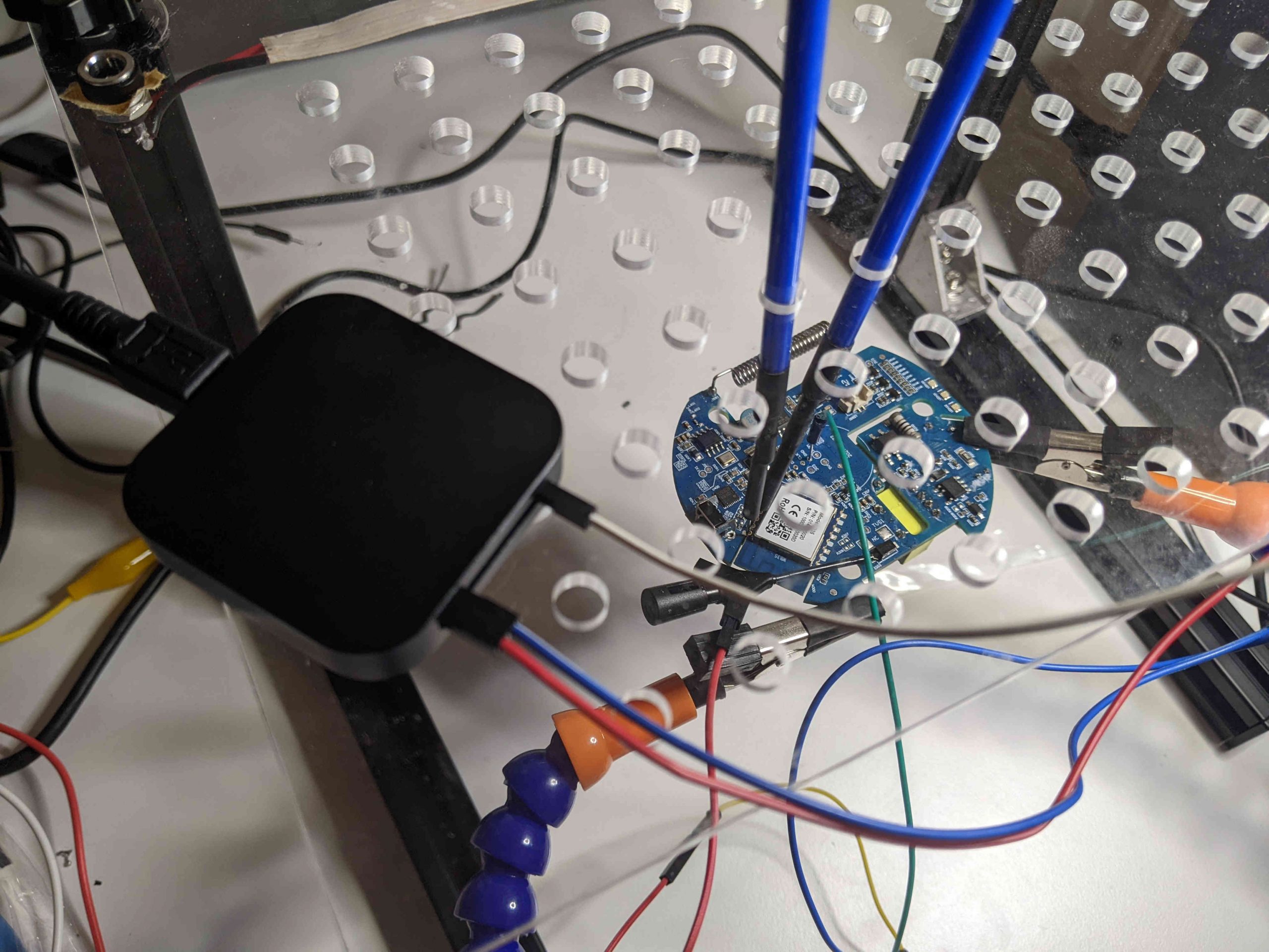
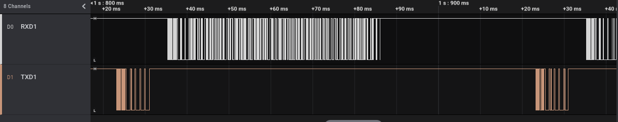
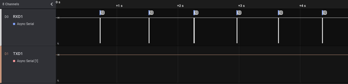
Once connected, we can run the Saleae software and power on our device. As we can see at the beginning of the track (when the device powers on) both pins pass from “Low” (~0V) to “High” (~3.3V) and then we can see some sort of potential communications (the vertical lines):
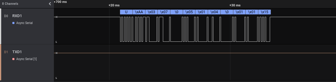
If we zoom into the sections in which we saw the vertical lines, we can clearly see that probably some data is transmitted on those pins:
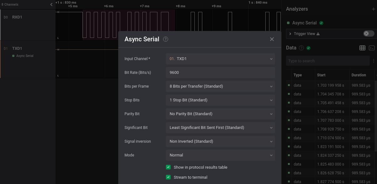
We know from the Tuya documentation that this port should be an UART port. The Saleae software already implements some modules name “Analyzers” able to decode many different protocols, including this one (named “Async Serial”). We can go to the “Analyzers” section (at the right) and add a new analyzer of type “Async Serial” on each of our two channels (that I renamed RXD1 and TXD1 for convenience). To be correctly interpreted, the UART protocol requires some parameters, among which the baud rate, the number of data bits and stop bits and the presence of a parity bit. Old versions of the Saleae software implemented auto-detection of the baud rate while newer ones don’t have this feature anymore. Anyhow, there are simple ways to manually estimate this value or we can use a dedicated Saleae plugin for the job, as described in the Saleae Support website. For data, stop and parity bit we can follow a trial-and-error approach, but usually these protocols use only a couple of different configurations.
Our “Async serial” parameters are the following:
We can add this analyzer to both our channels and have a look at the decoded data (with a right click on the data we can select different data visualizations: binary, decimal, hexadecimal or ascii):
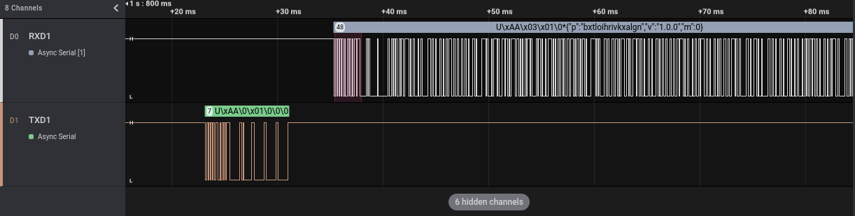
UART ports work this way: the TX pin of one party is connected to the RX of the other and vice-versa. Each pin is used by a party to transmit and by the other to receive. The names I used in the screenshots are related to the Tuya side and consequently:
- In TXD1 there are communications from the Tuya WiFi module to the ARM micro-controller
- in RXD1 there are communications from the ARM micro-controller to the Tuya WiFi module
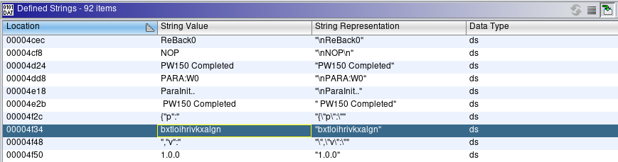
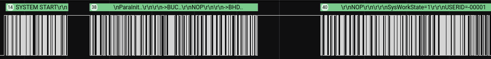
So, after the boot, the Tuya module sends 7 bytes to the ARM microcontroller, that answers with 6 bytes followed by a JSON string. The “p” JSON value seems to contain a random value, maybe a secret. We can easily find this string in the firmware we dumped in Part 2 of this series of articles, with the help of Ghidra’s String View:
By reaching the string (double-clicking on it) and looking at its XREFs, we can see that it seems to be present only in one location, that is:
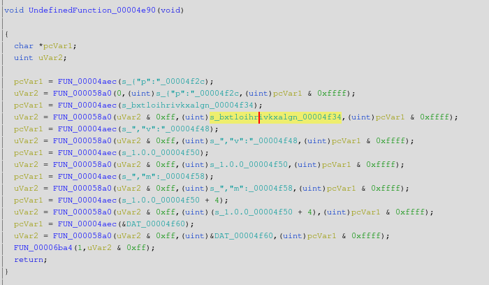
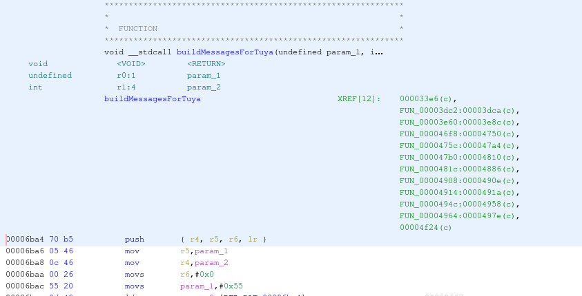
This seems to be the right place because this piece of code builds the JSON string we saw in the Saleae software. The JSON value is stored in the “uVar2” variable, which then is passed as an argument to FUN_00006ba4. The body of this function is:
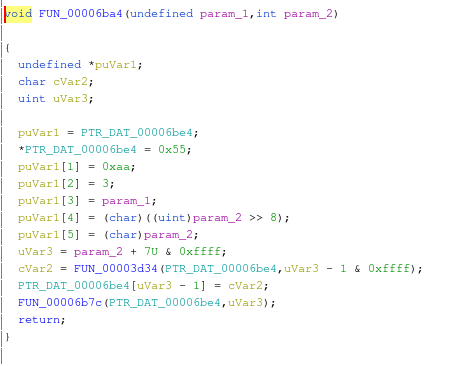
This function populates a structure with some bytes followed by our JSON string. These bytes are 0x55 (in ASCII ‘U’), 0xAA, 0x03, that are exactly the bytes we read using Saleae. If we look at the other communications dumped by Saleae, we can easily see that all messages from the ARM micro-controller to the Tuya module start this way, as in the following example:
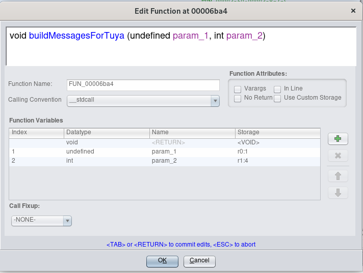
Probably, the function “FUN_00006ba4” builds and maybe sends the messages from the ARM micro-controller to the Tuya module. We can rename the function n Ghidra to reflect what we just discovered, by clicking on the function name with the right mouse button and selecting “Edit Function Signature”:
The XREFs of that function can be a good starting point to analyze the communications between the ARM micro-controller and the Tuya module:
But for now, let’s come back to the Saleae to look at the data transmitted on the UART port when a particular event occurs.
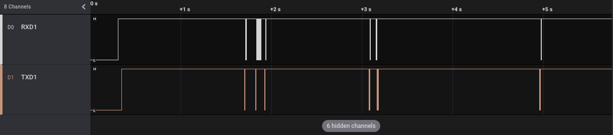
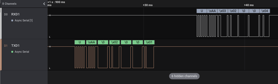
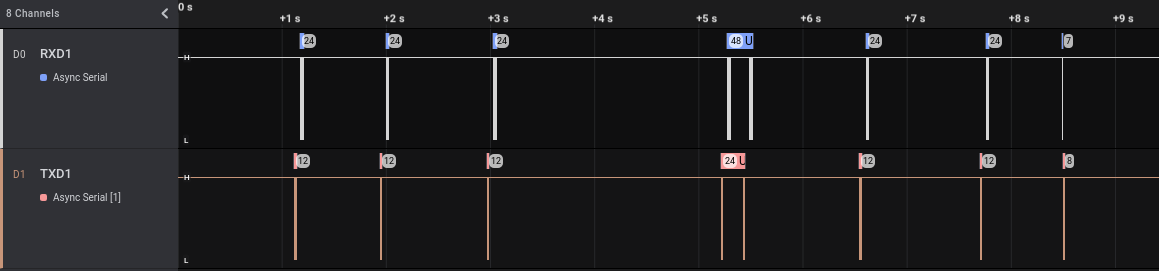
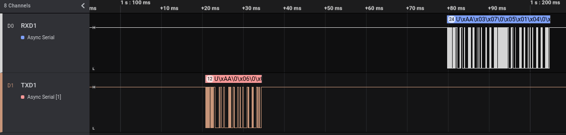
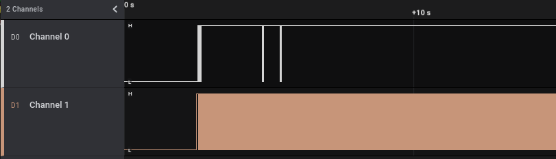
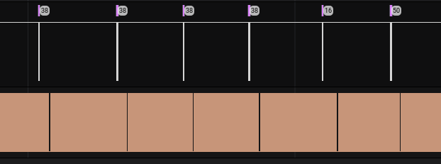
First, we will analyze what is transmitted when the user enables and disables the alarm using the 433 Mhz remote control (NB: we will use the 433 Mhz remote control to enable/disable the alarm but at the moment we are analyzing the UART port used by the device to talk to the WiFi module, not the 433 one that is used only to trigger an event). We will start the Saleae acquisition and then enable and disable the alarm three times, for a total of 6 communications. As we can see in the following screenshot, the six communications can be seen quite clearly in the Saleae acquired track on channel D0:
In this picture we can see that when we enable/disable the alarm with the remote button there is a unidirectional communication from the ARM micro-controller to the Tuya WiFi module. Probably the ARM micro-controller enables/disables the alarm and then notifies the change to the WiFi module, which in turns will send this information to the Tuya cloud (this alarm can be controlled using a mobile application).
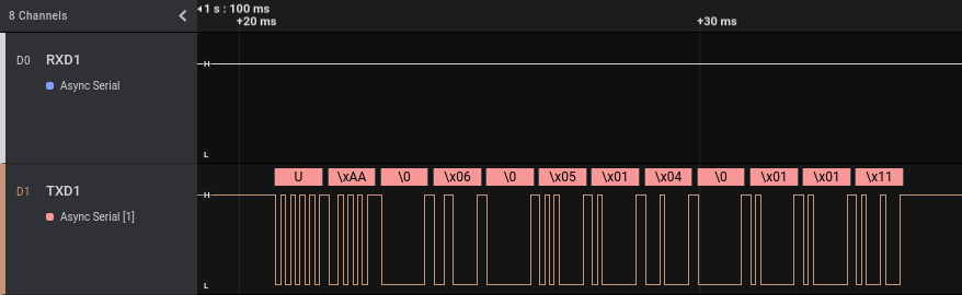
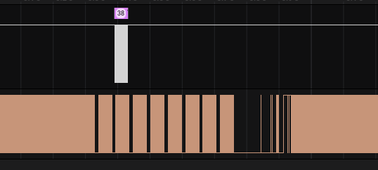
We can zoom on a single event (in this example an “enable” one) to see the transmitted bytes:
As with the other communications, the data starts with \x55 (‘U’ in ASCII), \xAA and \x03. If we zoom on a different “enable” event we can see that it is always composed by exactly the same bytes.
Now, let’s record another track on our Saleae, having a look at what it is transmitted when the user enables and disables the alarm using the Android application, instead of the 433 Mhz remote control. We will start the Saleae acquisition again and then enable and disable the alarm three times, for a total of 6 communications:
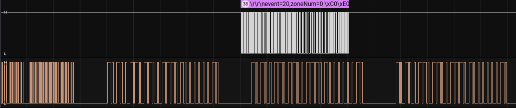
This time we have some data on both channels. We can see that in the track there are more than six events, with two of them (the central ones) different from the other six in each of the two tracks. These events can be related to some other communications from the device and its Tuya Wi-Fi module, potentially not directly related to the enable/disable actions. Let’s zoom on a single “enable” event:
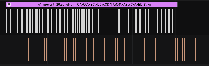
As we can see, we have a communication from the Tuya module to the ARM micro-controller chip, followed by an answer. This makes sense: we enable the alarm from the Android application, Tuya cloud sends a message that is received by the WiFi module that in turns sends a message to the ARM micro-controller. With a little more zoom we can read more easily the transmitted data:
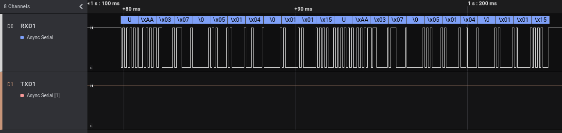
As before, if we look at the different “enable” events, the transmitted bytes are always exactly the same. But we also can note another thing. The answer from the ARM micro-controller to the Tuya module contains exactly the same data transmitted when we enabled the alarm using the 433 Mhz remote control, only replicated two times.
Well, more for fun than for security analysis purposes, we can try to enable and disable our smart alarm by replaying the messages from the Tuya module to the ARM micro-controller. This attack requires physical access to the smart alarm and it is also necessary to remove the Tuya wireless module from the board because otherwise it will interfere with our communications (and consequently it is not a super-realistic situation…). For this test I bought another smart alarm of the same model, I registered it with the mobile application and then I removed the Tuya module.
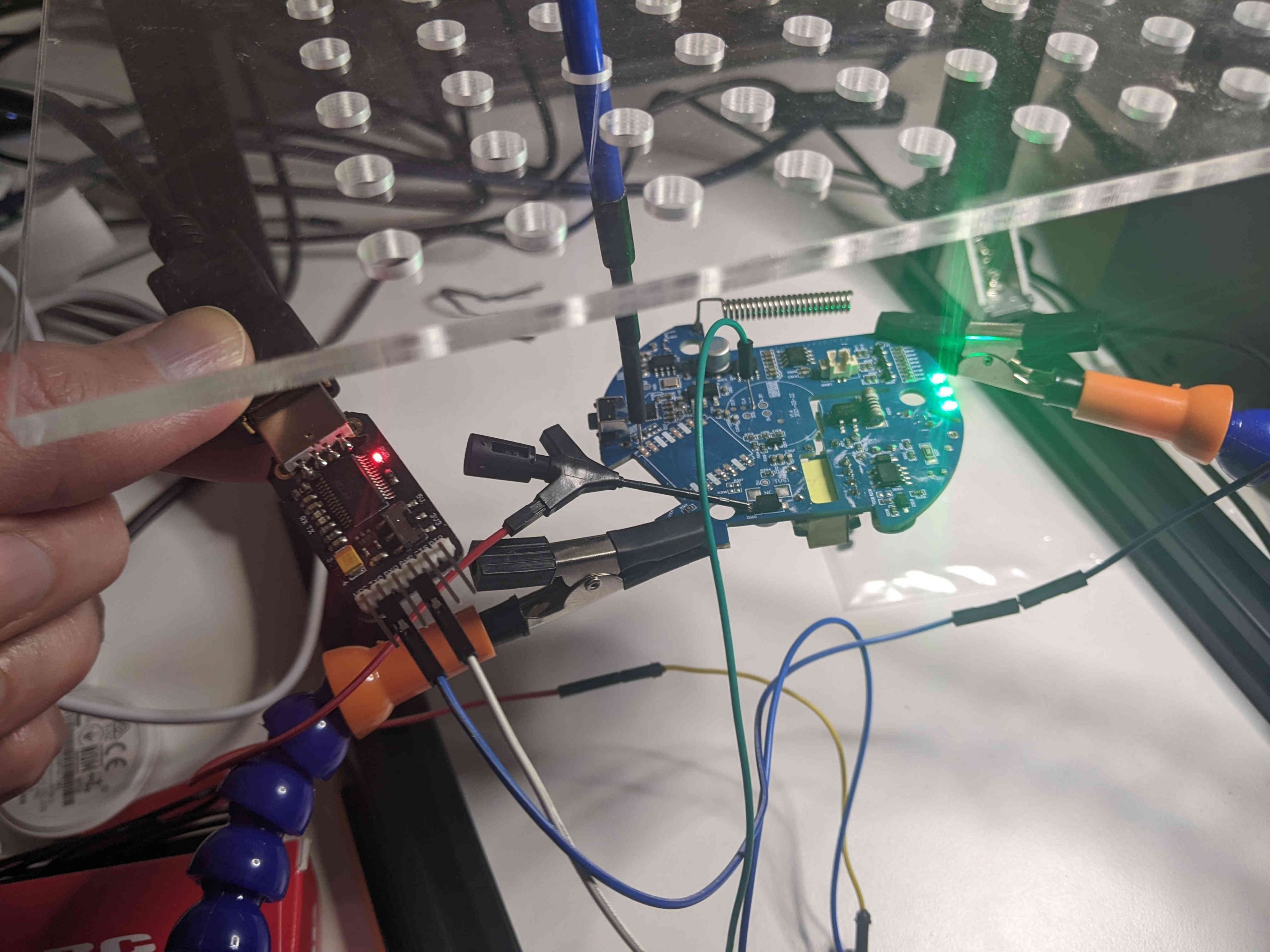
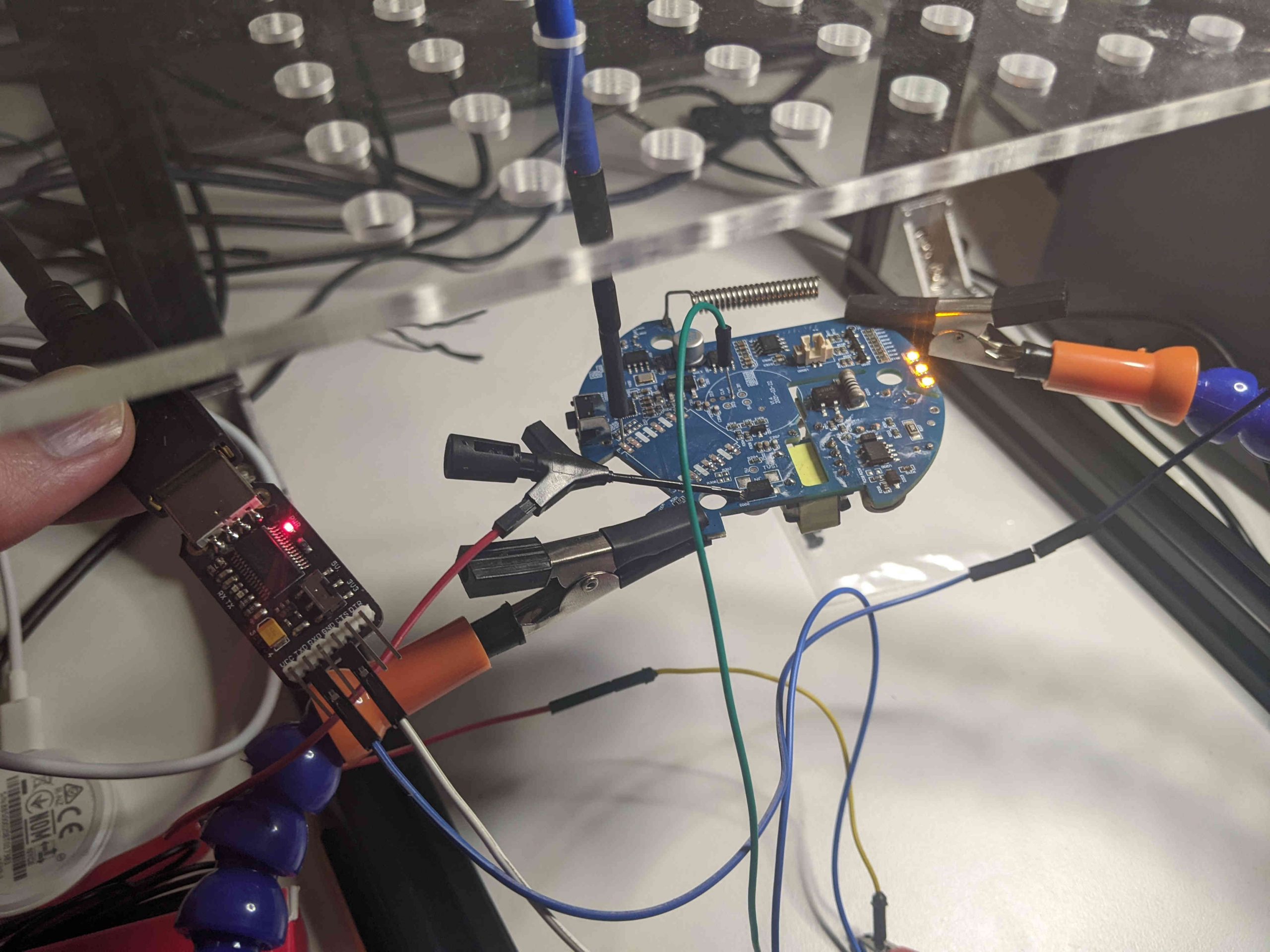
To send the fake messages, we will use a USB to TTL module, a small device created to connect a UART port to the USB port of a computer. After removing the Tuya module, we will connect the pin used by Tuya TXD1 to the TX pin of the USB to TTL module and the GND of the module to the GND of our circuit (if we want also to read the traffic from the ARM micro-controller we can connect the pin used by Tuya RXD1 to the RX pin of the USB to TTL module). The following picture show the connections (the alarm is “green” because it is in the “disabled” state):
To communicate using the UART port I will use moserial terminal emulator, but there exist many alternatives (like minicom).
We have to configure the communication parameters with the same parameter we used in the “Analysis” module of the Saleae software:
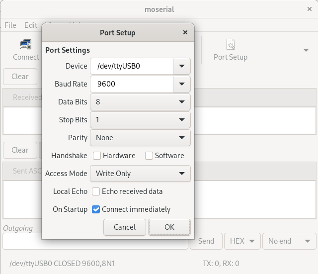
Then we can extract the “enable” command from the Saleae dump (0x55AA00060005010400010111) and send it with moserial (after connecting with the button “Connect”):
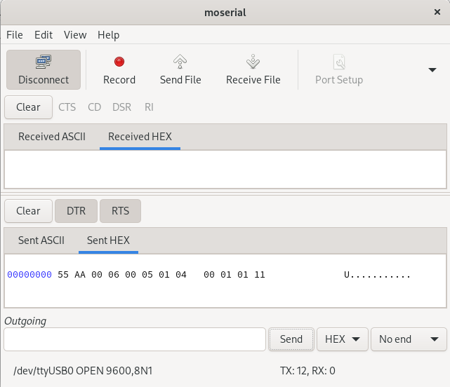
The result is that the alarm passes from the “disabled” state (green lights) to the “enabled” one (orange lights):
With the same procedure we can also do the reverse process (i.e., disable the alarm), using the HEX string 0x55AA00060005010400010010. This attack is for sure fun, but quite impractical in a real situation! 
UART Port 2 – Tuya module
According to the datasheet, the Tuya module includes a second UART port, whose PINs are named TXD2 and RXD2:
According to the documentation, this port should be disabled but it is always best to check if something passes through it.
Unfortunately, as stated in the datasheet no data passed through that port, neither during boot nor during various events. So, for now let’s move to the last port we want to analyze today.
RF and TX1 port on the board
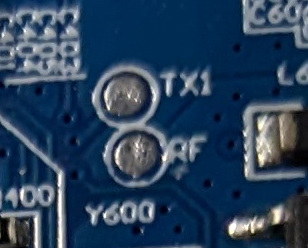
The last port we will analyze in this article is the one physically located between the 433 Mhz chip and the ARM Micro-controller (see the first picture of the post). It is made up of two pins: one named “TX1” (maybe the transmission pin of a UART port?) and other named “RF” (maybe radio frequency?):
Well, let’s have a look at it using the Saleae Logic Analyzer. We connect channel 0 of the Saleae to the “TX1” pin and channel 1 to the “RF” pin (besides GND pin, that should always be connected), start the Logic Analyzer software and then boot our smart alarm. The resulting track is the following:
In channel 0 (pin “TX1”) we have only a few initial communications and then silence. In channel 1 we apparently have tons of communications.
Let’s start the analysis from channel 0. We add the usual “Async Serial” analyzer on the Saleae software to check if our protocol guess was correct and that pin is a UART pin, zooming on the first communication after the boot:
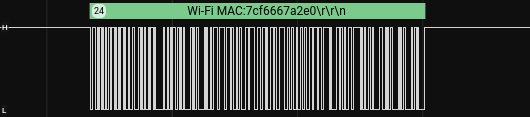
Our guess was correct: the “TX1” pin is the transmission pin of an UART port. We see some meaningful data, including a user identifier in the third block. If we zoom on the other communications, we can see that also the WiFi MAC address is transmitted:
Now, let’s focus on channel 1 (the “RF” pin). This channel from a first look seems to be full of communications but often when we have such a high traffic volume what we have is only the continuous noise of an analog port. We can try to put an “Async Serial” analyzer also here, but as we can see it is hard to be correct:
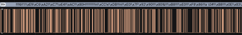
All the ‘!’ in the data decoded by the analyzer are errors, which shows that we configured a wrong analyzer.
Before digging into the meaning of this “RF” pin, let’s record some more data on target two pins during specific events. We will record a new track while pushing six times a button in the remote 433 Mhz control. The result is the following:
We can notice a couple of interesting things:
- When we push a button, information is transmitted on the UART TX1 pin (we will zoom on it in a moment)
- After we push a button there always is a change in the flow of the RF pin (it looks like an empty space from the current level of zoom; we will zoom on it in a moment)
If we zoom in a little, we can see that we have some changes in the flow of the “RF” pin, starting before (and not after as it looked before zooming) the transmission of the information on the “TX1” pin:
By zooming a little more we can see that when a button is pushed, the same wave is transmitted multiple time on the “RF” pin and a serial message is sent in the “TX1” pin after the first of these similar waves:
Let’s zoom a little more, to read the message on the first channel and to analyze the wave on the second channel:
The message on the pin of the UART port gives us some information, but what can be the recurring signal on the other pin? Recall the name of the pin: “RF” (probably radio frequency). In the part 3 of this series of articleswe analyzed the radio signals received on band 433 Mhz when buttons were pushed. Let’s resume the picture of demodulated form of that signal from the the previous article:
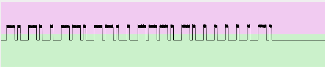
Does it look familiar? Let’s compare it with the wave of the “RF” pin:
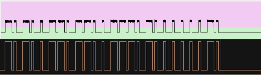
It is exactly the same wave! That pin resides in the middle of the connection between the chip responsible to receive the 433 Mhz signals and the ARM micro-controller. The latter receives the signal from the former, decodes it and then processes the contained command. Probably the “RF” and “TX1” pins are present on the board for debugging purposes, allowing an easy inspection of the radio-frequency received signals (pin “RF”) and how they are handled by the ARM micro-controller (pin “TX1”). The wave that fills the “RF” pin when no transmissions occur is the noise of that analog port and does not contain any information.
And for this article, this is all.
Cheers!
转载请注明:A journey into IoT – Unknown Chinese alarm – Part 4 – Internal communications | CTF导航